Mazda CX 7. Manual - part 134
CHARGING SYSTEM [L3 WITH TC]
01-17–7
01-17
9. Turn the following electrical loads on and verify that the current reading increases more than the minimum
value indicated below.
— If it is not as specified, go to the PCM and generator shearing inspection. (See 01-17-7 PCM and generator
shearing inspection.)
• Headlights (high-beam)
• Blower motor (HI)
• Rear window defroster
• Brake lights
Generator generated current minimum value
70 % of the nominal output current (nominal output current: 110 A)
[Ambient temp. 20
°C {68 °F}, voltage 13.0— 15.0 V, both engine and generator are hot]
PCM and generator shearing inspection
1. Connect the M-MDS to the DLC-2.
2. Inspect as follows:
DLC-2
acxuuw00002019
Step
Inspection
Action
1
Measure the generator terminal B voltage when the
electrical loads
*1
are on and off.
15 V or more
Go to Step 2.
13— 15 V
Normal
*2
13 V or less
Go to Step 3.
2
Monitor the ALTT V PID using the M-MDS, or measure the
voltage of PCM terminal 2AJ using a tester. Is the voltage
between 13 and 15 V ?
Yes
Go to Step 4.
No
PCM input error.
3
Monitor the ALTT V PID using the M-MDS, or measure the
voltage of PCM terminal 2AJ using a tester. Is the voltage
between 13 and 15 V ?
Yes
Go to Step 5.
No
PCM input error.
4
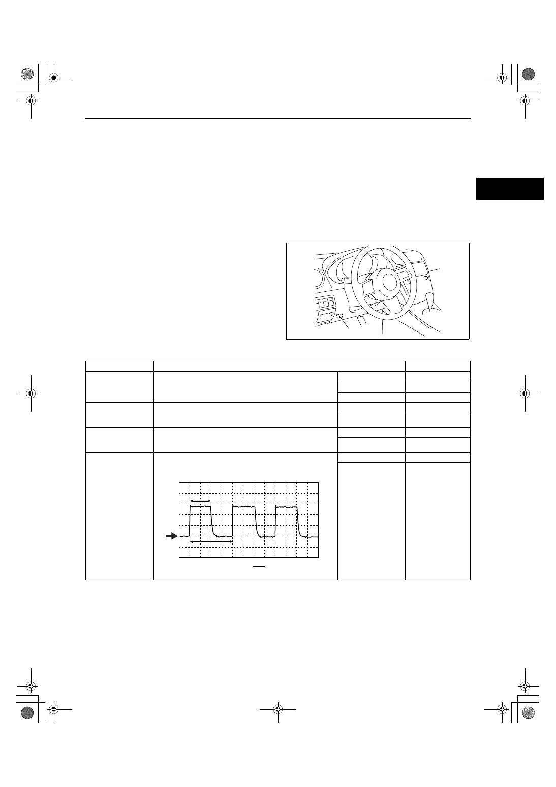
Monitor the ALTF PID using the M-MDS, or calculate the
duty value of the PCM terminal 2AI using an oscilloscope.
Is the duty value 100 % ?
Yes
PCM input error.
No
PCM, generator, or
both are not
normal.
0V
A
B
B
A
x 100 (%) = DUTY (%)
1871-1U-06B(01-17).fm 7 ページ 2006年3月15日 水曜日 午前10時49分