Mazda CX 7. Manual - part 122


  Index      Mazda     Mazda CX 7 - service repair manual 2007 year


Search            


Content   ..  120  121  122  123   ..


Mazda CX 7. Manual - part 122


FUEL SYSTEM [L3 WITH TC]

01-14–9

01-14

16. Install in the reverse order of removal.
17. Complete the “AFTER REPAIR PROCEDURE”. (See01-14-4 AFTER REPAIR PROCEDURE[L3 WITH TC].)
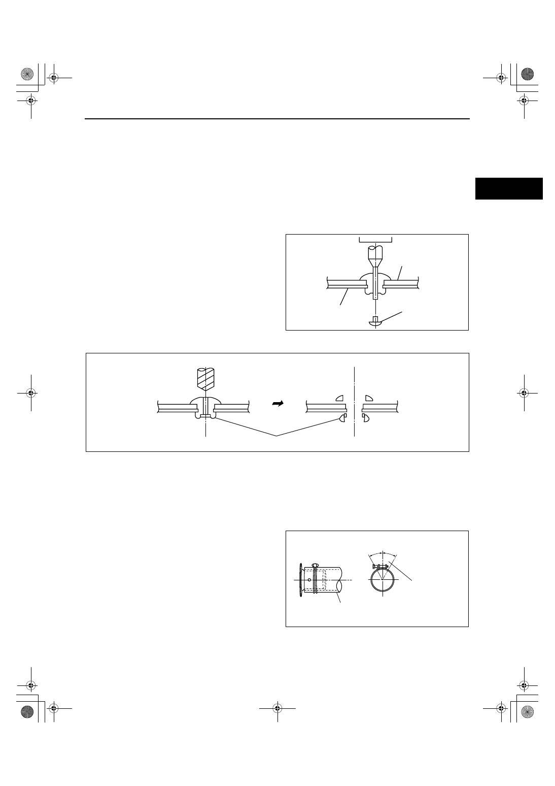
Rivet Removal Note

Caution

• Be careful not to damage the fuel tank when removing the rivet. If the fuel tank is damaged, it may 

cause fuel leakage.

Note

• The insulator is installed using rivets.

• When resin stalling the rivet, install the same rivet or M5 bolt and nut.

1. Push out the mandrel using a hammer and punch 

(2—2.8 mm {0.08—0.11 in} diameter).

2. Remove the flange using a drill (5 mm {0.20 in} drill bit).

Fuel-filler Pipe Removal Note

1. Remove the rear tire (LH).
2. Remove the mudguard (LH).
3. Remove the air filter.
4. Remove the fuel-filler pipe.

Joint Hose Installation Note

1. Install the joint hose and clamp as shown in the 

figure.

HAMMER

INSULATOR

FUEL TANK

MANDREL

acxuuw00000260

DRILL

FLANGE

acxuuw00000261

JOINT HOSE

CLAMP 
TIGHTENING AREA

30

°

30

°

VIEW A

acxuuw00000265

1871-1U-06B(01-14).fm  9 ページ  2006年3月15日 水曜日 午前10時45分

FUEL SYSTEM [L3 WITH TC]

01-14–10

Breather Hose Installation Note

1. Install the breather hose and clamp as shown in 

the figure.

End Of Sie

WM: FUEL SHUT-OFF VALVE

FUEL SHUT-OFF/ROLLOVER VALVE INSPECTION[L3 WITH TC]

id011439801800

Caution

• Disconnecting/connecting the quick release connector without cleaning it may cause damage to 

the fuel pipe and quick release connector. Always clean the quick release connector joint area 
before disconnecting/connecting using a cloth or soft brush, and make sure that it is free of 
foreign material.

Note

• This inspection is for fuel shut-off valve and rollover valve integrated in the fuel tank.

1. Disconnect the quick release connector and the fuel pump unit connector. (See01-14-11 FUEL PUMP UNIT 

REMOVAL/INSTALLATION[L3 WITH TC].)

2. Remove the fuel tank with the fuel pump unit. (See01-14-7 FUEL TANK REMOVAL/INSTALLATION[L3 WITH 

TC].)

3. Plug the port as shown in the figure.
4. Level the fuel tank.

5. Blow through port B and verify that there is airflow 

from port A.

• If there is no airflow, replace the fuel tank.

• If there is airflow, turn the fuel tank upside 

down, and proceed to Step 6.

6. Blow through port B and verify that there is no 

airflow from port A.

• If there is airflow, replace the fuel tank.

End Of Sie

WM: FUEL PUMP

45

°

45

°

VIEW B

CLAMP 
TIGHTENING AREA

BREATHER HOSE

acxuuw00000266

FUEL PUMP UNIT

A

B

C

PLUG

PLUG

acxuuw00000122

FUEL PUMP UNIT

PLUG

A

B

C

PLUG

acxuuw00000123

1871-1U-06B(01-14).fm  10 ページ  2006年3月15日 水曜日 午前10時45分

FUEL SYSTEM [L3 WITH TC]

01-14–11

01-14

FUEL PUMP UNIT REMOVAL/INSTALLATION[L3 WITH TC]

id011439800900

Warning

• Fuel line spills and leakage are dangerous. Fuel can ignite and cause serious injuries or death and 

damage. Fuel can also irritate skin and eyes. To prevent this, always complete the “Fuel Line 
Safety Procedure”.

• Fuel line spills and leakage are dangerous. Fuel can ignite and cause serious injuries or death and 

damage. Fuel can also irritate skin and eyes. To prevent this, before performing the fuel pump unit 
removal/installation, always complete the “Fuel Leak Inspection After Fuel Pump Unit 
Installation”.

• A person charged with static electricity could cause a fire or explosion, resulting in death or 

serious injury. Before draining fuel, make sure to discharge static electricity by touching the 
vehicle body.

Caution

• Because the fuel tank is constructed such that the fuel level is higher than the installation surface 

of the fuel pump, fuel leakage could occur. If the fuel gauge indicates a fuel level of half or more, 
perform the following Steps 1-6 to drain approx. 10 L {11 US gal, 8.8 lmp gal} of fuel.

• Disconnecting/connecting the quick release connector without cleaning it may possibly cause 

damage to the fuel pipe and quick release connector. Always clean the quick release connector 
joint area before disconnecting/connecting using a cloth or soft brush, and make sure that it is 
free of foreign material.

• To prevent the SST from coming off the fuel pump cap while performing the work, always perform 

the removal/installation procedure with 2 people. One person presses the SST against cap from 
directly above, while the other person rotates the SST.

1. Complete the “BEFORE REPAIR PROCEDURE”. (See01-14-4 BEFORE REPAIR PROCEDURE[L3 WITH 

TC].)

2. Remove the rear seat cushion.
3. Remove the service hole cover.

4. Disconnect the quick release connector 

connected to the fuel pump unit.

5. Connect a long hose to the disconnected quick 

release connector and drain the fuel into a 
container used for collecting gasoline.

SERVICE HOLE COVER

acxuuw00000510

HOSE

FRONT

QUICK RELEASE 
CONNECTOR

acxuuw00000181

1871-1U-06B(01-14).fm  11 ページ  2006年3月15日 水曜日 午前10時45分

FUEL SYSTEM [L3 WITH TC]

01-14–12

6. Start the fuel pump using the following procedure.

Using M-MDS

1. Connect the M-MDS to the DLC-2.
2. Using the simulation function “FP”, start the 

fuel pump.

Without using M-MDS

1. Remove the fuel pump relay.

Caution

• Short the specified terminals because 

shorting the wrong terminal of the main 
fuse block may cause malfunctions.

2. Using a jumper wire, short fuel pump relay 

terminals C and D in the main fuse block.

3. Connect the negative battery cable and 

operate the fuel pump.

Caution

• The fuel pump could be damaged if it is 

operated (fuel pump idling) while there is 
no fuel in the fuel tank. Verify the amount 
of fuel being discharged from the hose 
and stop operation of the fuel pump 
when essentially no fuel is being 
discharged.

7. When essentially no fuel is being discharged, stop the fuel pump.

Using M-MDS

1. Using the simulation function “FP”, stop the fuel pump.

Without using M-MDS

1. Turn the ignition switch to LOCK position to stop the fuel pump.
2. Disconnect the jumper wire from the check connector.

8. Disconnect the negative battery cable.
9. Remove the fuel pump bracket installation screws.

10. Remove in the order indicated in the table.

11. Install in the reverse order of removal.
12. Complete the “AFTER REPAIR PROCEDURE”. (See01-14-4 AFTER REPAIR PROCEDURE[L3 WITH TC].)

End Of Sie

DLC-2

acxuuw00000288

A

E

C

D

MAIN FUSE BLOCK 
(FUEL PUMP RELAY)

acxuuw00000183

4

3

1

2

5

6

R

acxuuw00000289

1

Connector

2

Quick release connector
(See01-14-19 QUICK RELEASE CONNECTOR 
REMOVAL/INSTALLATION[L3 WITH TC])

3

Quick release connector
(See01-14-19 QUICK RELEASE CONNECTOR 
REMOVAL/INSTALLATION[L3 WITH TC])

4

Fuel pump unit

5

Packing

6

Fuel pump bracket

1871-1U-06B(01-14).fm  12 ページ  2006年3月15日 水曜日 午前10時45分


Content   ..  120  121  122  123   ..