Mazda CX 7. Manual - part 107


  Index      Mazda     Mazda CX 7 - service repair manual 2007 year


Search            


Content   ..  105  106  107  108   ..


Mazda CX 7. Manual - part 107


MECHANICAL [L3 WITH TC]

01-10–29

01-10

OIL CONTROL VALVE (OCV) REMOVAL/INSTALLATION[L3 WITH TC]

id011039801300

1. Disconnect the negative battery cable.
2. Remove the charge air cooler. (See01-13-5 INTAKE AIR SYSTEM REMOVAL/INSTALLATION[L3 WITH TC].)
3. Remove the ignition coils. (See01-18-2 IGNITION COIL REMOVAL/INSTALLATION[L3 WITH TC].)
4. Disconnect the wiring harness.
5. Remove the ventilation hose.
6. Remove the cylinder head cover. (See01-10-10 TIMING CHAIN REMOVAL/INSTALLATION[L3 WITH TC].)
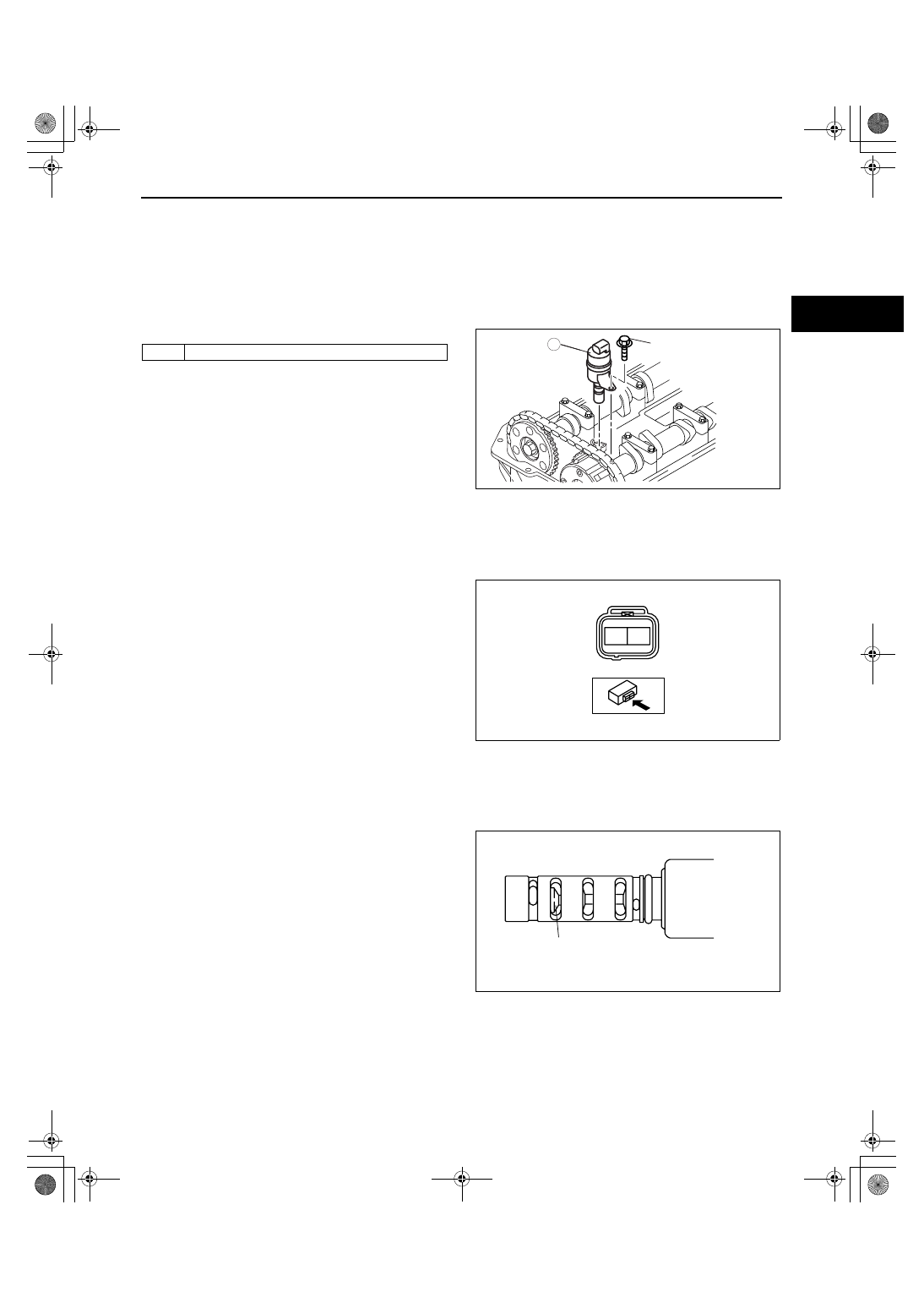
7. Remove in the order indicated in the table.
8. Install in the reverse order of removal.

Tightening torque

8.0— 11.5 N·m {82— 117 kgf·cm, 71— 101 

in·lbf}

End Of Sie

OIL CONTROL VALVE (OCV) INSPECTION[L3 WITH TC]

id011039801400

Coil Resistance Inspection

1. Disconnect the negative battery cable.
2. Disconnect the OCV connector.
3. Measure the coil resistance between terminals A 

and B using a tester.

• If it is not within the specification, replace the 

OCV.

OCV resistance

6.9— 7.9 ohms [20

°C {68°F}]

4. Connect the OCV connector.
5. Connect the negative battery cable.

Spool Valve Operation Inspection

1. Disconnect the negative battery cable.
2. Disconnect the OCV connector.
3. Remove the OCV. (See01-10-29 OIL CONTROL VALVE (OCV) REMOVAL/INSTALLATION[L3 WITH TC].)
4. Verify that the spool valve in the OCV is in the 

maximum valve timing retard position as indicated 
in the figure.

• If not as specified, replace the OCV.

5. Verify that the battery is fully charged.

• If not as specified, recharge the battery.

1

OCV

1

8.0—11.5 {82—117,
71—101}

N·m {kgf·cm, in·lbf}

acxuuw00000138

A

B

acxuuw00000139

SPOOL VALVE
(MAXIMUM VALVE TIMING RETARD POSITION

acxuuw00000140

1871-1U-06B(01-10).fm  29 ページ  2006年3月15日 水曜日 午前10時39分

MECHANICAL [L3 WITH TC]

01-10–30

6. Apply battery positive voltage between the OCV 

terminals and verify that the spool valve operates 
and moves to the maximum valve timing advance 
position.

• If not as specified, replace the OCV.

Note

• When applying battery positive voltage 

between the OCV terminals, the connection 
can be either of the following:

— Positive battery cable to terminal A, 

Negative battery cable to terminal B

— Positive battery cable to terminal B, 

Negative battery cable to terminal A

7. Stop applying battery positive voltage and verify that the spool valve returns to the maximum valve timing retard 

position.

• If not as specified, replace the OCV. (See01-10-29 OIL CONTROL VALVE (OCV) REMOVAL/

INSTALLATION[L3 WITH TC].)

8. Connect the OCV connector.
9. Connect the negative battery cable.

End Of Sie

WM: ENGINE COMPLETE

A

B

acxuuw00000139

VALVE TIMING 
ADVANCE

VALVE TIMING 
RETARD

SPOOL VALVE
(MAXIMUM VALVE TIMING ADVANCE POSITION)

acxuuw00000142

1871-1U-06B(01-10).fm  30 ページ  2006年3月15日 水曜日 午前10時39分

MECHANICAL [L3 WITH TC]

01-10–31

01-10

ENGINE REMOVAL/INSTALLATION[L3 WITH TC]

id011039800400

Warning

• Fuel vapor is hazardous. It can very easily ignite, causing death, serious injury, or damage. Always 

keep sparks and flames away from fuel.'

• Fuel line spills and leakage from the pressurized fuel system are dangerous. Fuel can easily ignite 

and cause serious injury or death and damage. Fuel can also irritate skin and eyes. To prevent 
this, always perform the Fuel Line Safety Procedure. (See01-14-4 BEFORE REPAIR 
PROCEDURE[L3 WITH TC].)

1. Disconnect both battery cable.
2. Remove the battery and battery tray. (See01-17-2 BATTERY REMOVAL/INSTALLATION[L3 WITH TC].)
3. Remove the charge air cooler duct. (See01-13-5 INTAKE AIR SYSTEM REMOVAL/INSTALLATION[L3 WITH 

TC].)

4. Remove the air cleaner. (See01-13-5 INTAKE AIR SYSTEM REMOVAL/INSTALLATION[L3 WITH TC].)
5. Remove the front tire. (See02-12-4 WHEEL UNIT REMOVAL/INSTALLATION.
6. Remove the under cover, splash shield and mudguard.
7. Remove the drive belt. (See01-10-3 DRIVE BELT REMOVAL/INSTALLATION[L3 WITH TC].)
8. Disconnect the heater hose. (See07-11-2 A/C UNIT REMOVAL/INSTALLATION.
9. Disconnect the radiator hose. (See01-12-8 RADIATOR REMOVAL/INSTALLATION[L3 WITH TC].

10. Disconnect the brake vacuum hose.
11. Disconnect the fuel hose and vacuum hose. (See 01-14-19 QUICK RELEASE CONNECTOR REMOVAL/

INSTALLATION[L3 WITH TC].)

12. Disconnect the selector cable from the transaxle side. (See05-18-7 SELECTOR LEVER COMPONENT 

REMOVAL/INSTALLATION.)

13. Disconnect the wiring harnesses.
14. Drain the engine coolant (See01-12-5 ENGINE COOLANT REPLACEMENT[L3 WITH TC].)
15. Drain the automatic transaxle fluid (ATF). (See05-17-11 AUTOMATIC TRANSAXLE FLUID (ATF) 

REPLACEMENT[AW6A-EL, AW6AX-EL].)

16. Remove the propeller shaft (AWD). (See03-15-3 PROPELLER SHAFT REMOVAL/INSTALLATION.)
17. Remove the front pipe and rear HO2S. (See01-15-2 EXHAUST SYSTEM REMOVAL/INSTALLATION[L3 WITH 

TC].)

18. Disconnect the front drive shaft (RH) from the joint shaft side. (See03-13-12 FRONT DRIVE SHAFT 

REMOVAL/INSTALLATION.)

19. Disconnect the front drive shaft (LH) from the transaxle side. (See03-13-12 FRONT DRIVE SHAFT REMOVAL/

INSTALLATION.)

20. Remove the A/C compressor with the pipes still connected. (See07-11-13 A/C COMPRESSOR REMOVAL/

INSTALLATION.)

Note

• Position and secure the A/C compressor out of the way with rope.

21. Remove in the order indicated in the figure.
22. Install in the reverse order of removal.
23. Start the engine, and inspect and adjust the following:

• Air bleeding (See 06-14-3 AIR BLEEDING.) 

• Front wheel alignment (See 02-11-2 FRONT WHEEL ALIGNMENT.) 

• Bleed the air from the cooling system. (See01-12-5 ENGINE COOLANT REPLACEMENT[L3 WITH TC].)

• Runout and contact on pulley and belt

• Leakage of engine oil, engine coolant, automatic transmission fluid, or fuel.

• Ignition timing, idle speed and idle mixture (CO and HC)

• Engine accessories operation

24. Perform a road test and verify that there is no abnormal vibration or noise.

1871-1U-06B(01-10).fm  31 ページ  2006年3月15日 水曜日 午前10時39分

MECHANICAL [L3 WITH TC]

01-10–32

25.

B

A

3

2

4

74.5—104.9 {7.6—10.6, 55.0—77.3} 

74.5—104.9 
{7.6—10.6, 
55.0—77.3} 

66.6—93.1 
{6.8—9.4, 
50—68} 

66.6—93.1 {6.8—9.4, 
50—68} 

1

1

85.3—116.6 
{8.7—11.8, 
63.0—85.9} 

93.1—116.6 {9.5—11.8, 68.7—85.9} 

A

B

N·m {kgf·m, ft·lbf}

acxuuw00000185

1

No.1 engine mount
(See01-10-33 No.1 Engine Mount Removal Note.)
(See01-10-33 Engine Mount Installation Note.)

2

No.4 engine mount bracket
(See01-10-33 No.3 Engine Mount Rubber, No.4 
Engine Mount Bracket Removal Note.)
(See01-10-33 Engine Mount Installation Note.)

3

No.3 engine mount rubber
(See01-10-33 No.3 Engine Mount Rubber, No.4 
Engine Mount Bracket Removal Note.)
(See01-10-33 Engine Mount Installation Note.)

4

Engine and transaxle

1871-1U-06B(01-10).fm  32 ページ  2006年3月15日 水曜日 午前10時39分


Content   ..  105  106  107  108   ..