Mazda CX 7. Manual - part 106


  Index      Mazda     Mazda CX 7 - service repair manual 2007 year


Search            


Content   ..  104  105  106  107   ..


Mazda CX 7. Manual - part 106


MECHANICAL [L3 WITH TC]

01-10–27

01-10

2007 Mazda CX-7 Workshop Manual (1871–1U–06B)

Revised 9/2006 (Ref. No. R115/06) 

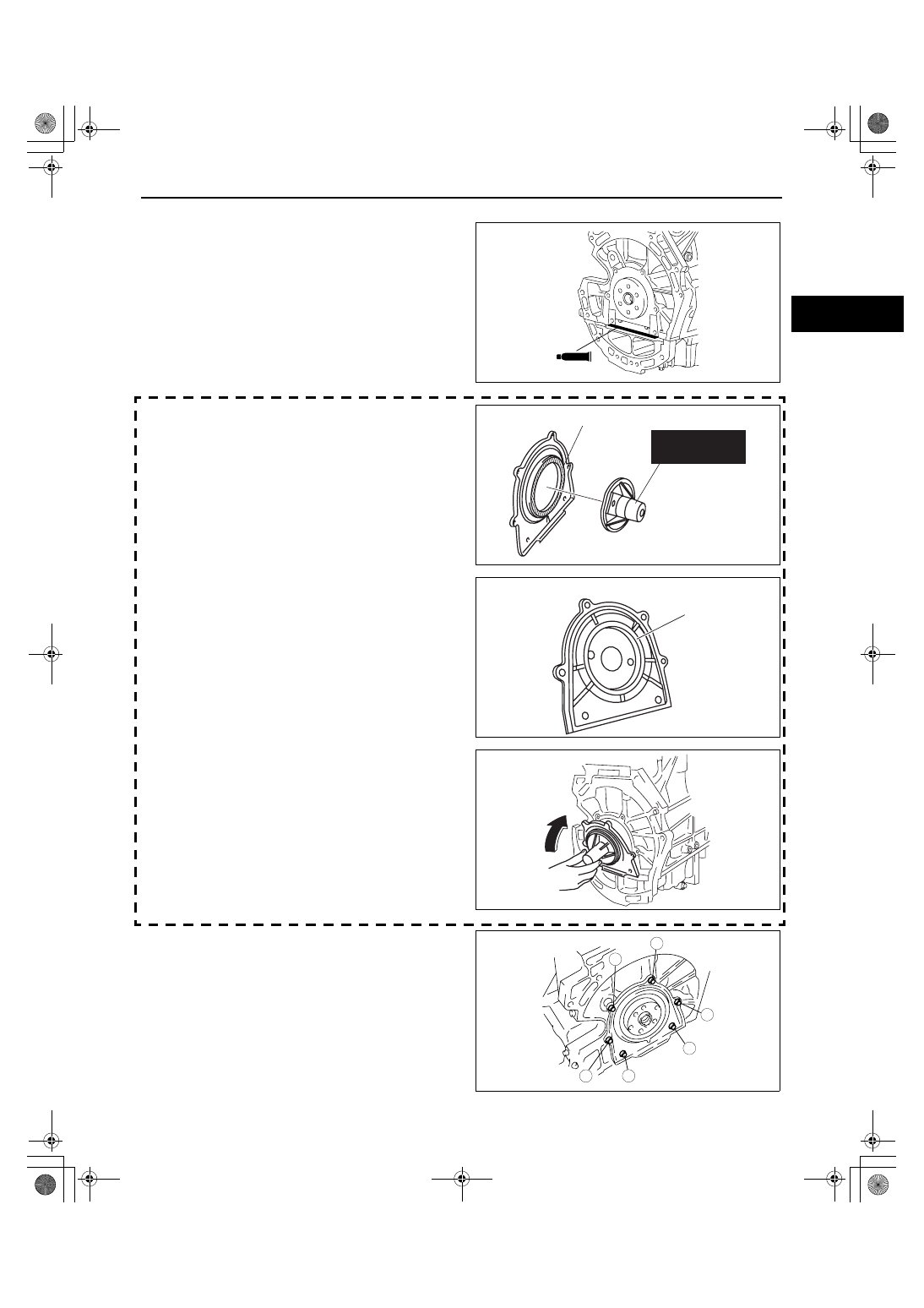
Rear Oil Seal Installation Note

1. Apply silicone sealant to the areas shown in the 

figure.

Caution

• Install the rear oil seal within 10 min of 

applying the silicone sealant.

Thickness

4.0— 6.0 mm {0.16— 0.23 in}

2. Apply clean engine oil to a new rear oil seal.

3. Install the SST to the non-woven fabric side of the 

rear oil seal.

4. From the back side of the rear oil seal, verify that 

there is no damage or separation in the lip area of 
the rear oil seal.

5. Install the rear oil seal to the engine as shown in 

the figure.

6. Tighten the rear oil seal installation bolts in the 

order shown in the figure.

Tightening torque

8.0— 11.5 N·m {82— 117 kgf·cm, 71— 101 

in·lbf}

End Of Sie

WM: VARIABLE VALVE TIMING ACTUATOR

SEALANT

acxuuw00000147

303-328 

(49 UN30 3328)

NON-WOVEN FABRIC

acxuuw00002559

BACK SIDE OF REAR OIL SEAL

LIP AREA

acxuuw00002560

acxuuw00002561

4

6

3

5

1

2

acxuuw00000149

MECHANICAL [L3 WITH TC]

01-10–28

2007 Mazda CX-7 Workshop Manual (1871–1U–06B)

VARIABLE VALVE TIMING ACTUATOR INSPECTION[L3 WITH TC]

id011039801200

Caution

• Due to the precision interior construction of the variable valve timing actuator, it cannot be 

disassembled.

1. Disconnect the negative battery cable.
2. Remove the charge air cooler. (See01-13-5 INTAKE AIR SYSTEM REMOVAL/INSTALLATION[L3 WITH TC].)
3. Remove the ignition coils. (See01-18-2 IGNITION COIL REMOVAL/INSTALLATION[L3 WITH TC].)
4. Remove the spark plugs. (See01-18-3 SPARK PLUG REMOVAL/INSTALLATION[L3 WITH TC].)
5. Disconnect the wiring harness.
6. Remove the ventilation hose.
7. Remove cylinder head cover. (See01-10-10 TIMING CHAIN REMOVAL/INSTALLATION[L3 WITH TC].)
8. Verify that the groove of the rotor and notch of the 

cover on the variable valve timing actuator are 
aligned and fitted.

• If they are not aligned, rotate the crankshaft in 

the direction of engine rotation two times and 
verify that they are aligned.

— If they will not align, replace the variable 

valve timing actuator.

• If under any condition, the variable valve 

timing actuator always makes a hitting noise 
directly after the camshaft exceeds maximum 
lift while rotating the crankshaft two times in 
the direction of engine rotation, replace the 
variable valve timing actuator as it has not 
been fixed.

9. Install the cylinder head cover. (See01-10-10 TIMING CHAIN REMOVAL/INSTALLATION[L3 WITH TC].)

10. Install the ventilation hose.
11. Connect the wiring harness.
12. Install the spark plugs. (See01-18-3 SPARK PLUG REMOVAL/INSTALLATION[L3 WITH TC].)
13. Install the ignition coils. (See01-18-2 IGNITION COIL REMOVAL/INSTALLATION[L3 WITH TC].)
14. Install the charge air cooler.   (See01-13-5 INTAKE AIR SYSTEM REMOVAL/INSTALLATION[L3 WITH TC].)
15. Connect the negative battery cable.

End Of Sie

VARIABLE VALVE TIMING ACTUATOR REMOVAL/INSTALLATION[L3 WITH TC]

id011039801100

Caution

• Remove the variable valve timing actuator and camshaft sprocket as a single unit.

Note

• The variable valve timing actuator and camshaft sprocket cannot be disassembled.

1. Referring to the valve clearance adjustment procedure, remove the variable valve timing actuator and the 

camshaft on the intake air side as a single unit. (See01-10-4 VALVE CLEARANCE INSPECTION/
ADJUSTMENT[L3 WITH TC].)

2. Remove the variable valve timing actuator.

(1) Place alignment marks on the camshaft and variable valve timing actuator as shown in the figure so that the 

variable valve timing actuator is re-assembled in its original position.

(2) Fix the camshaft in a vise.
(3) Loosen the variable valve timing actuator 

installation bolt.

End Of Sie

NOTCH

acxuuw00000143

MARK

acxuuw00000144

MECHANICAL [L3 WITH TC]

01-10-28–1

01–10

2007 Mazda CX-7 Workshop Manual (1871–1U–06B)

01-10-28

MECHANICAL [L3 WITH TC]

3. Install a new washer.
4. Install the variable valve timing actuator.

(1) Fix the camshaft in a vise.
(2) Align the marks on the camshaft and the 

variable valve timing actuator.

Caution

• If replacing with a new variable valve 

timing actuator, place alignment marks in 
the same positions as those prior to the 
replacement.

(3) Tighten the variable valve timing actuator 

installation bolt.

Tightening torque

69— 75 N·m {7.1— 7.6 kgf·m, 51— 55 ft·lbf}

5. Referring to the valve clearance adjustment procedure, install the variable valve timing actuator and camshaft 

on the intake air side as a single unit. (See01-10-4 VALVE CLEARANCE INSPECTION/ADJUSTMENT[L3 
WITH TC].)

End Of Sie

R

acxuuw00000145

MECHANICAL [L3 WITH TC]

01-10-28–2

2007 Mazda CX-7 Workshop Manual (1871–1U–06B)

THIS PAGE INTENTIONALLY

LEFT BLANK


Content   ..  104  105  106  107   ..