Mazda CX 7. Manual - part 105


  Index      Mazda     Mazda CX 7 - service repair manual 2007 year


Search            


Content   ..  103  104  105  106   ..


Mazda CX 7. Manual - part 105


MECHANICAL [L3 WITH TC]

01-10–23

01-10

2007 Mazda CX-7 Workshop Manual (1871–1U–06B)

Revised 3/2007 (Ref. No. R051/07) 

Camshaft Installation Note

1. Install the camshaft with No.3 cylinder cam aligned at TDC of compression stroke.

2. Carefully apply adhesive agent (Loctite 518 or 

962) to the area indicated in the figure so that it 
does not leak into the sliding part.

Thickness

1.0 mm {0.039 in}

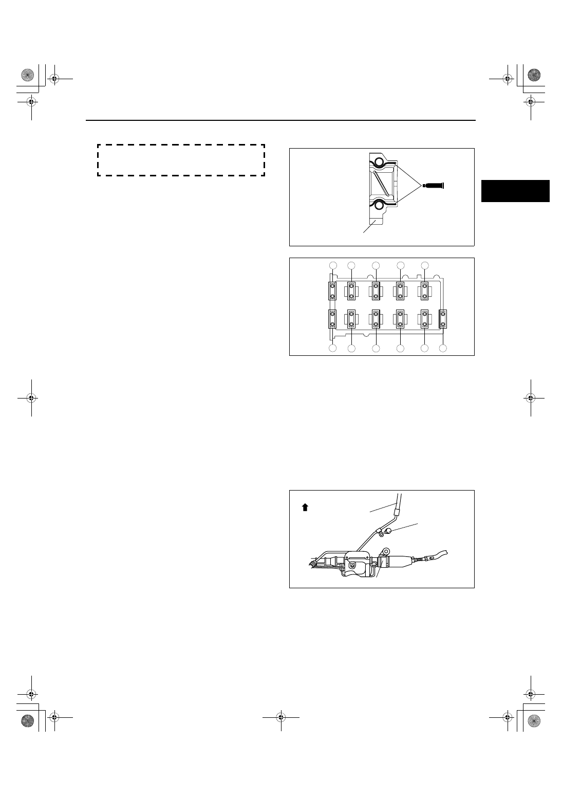
3. Install the camshaft caps and temporarily tighten 

the camshaft cap bolts evenly in two or three 
passes, and then tighten the camshaft cap bolts 
using the following two steps, in the order shown 
in the figure.

Tightening procedure

1. 5.0— 9.0 N·m {51— 91 kgf·cm, 45— 79 

in·lbf}

2. 14— 17 N·m {1.5— 1.7 kgf·m, 11— 12 ft·lbf}

End Of Sie

WM: FRONT OIL SEAL

FRONT OIL SEAL REPLACEMENT[L3 WITH TC]

id011039800800

1. Disconnect the negative battery cable.
2. Remove the under cover.
3. Remove the splash shield (RH).
4. Remove the charge air cooler. (See01-13-5 INTAKE AIR SYSTEM REMOVAL/INSTALLATION[L3 WITH TC].)
5. Remove the high pressure fuel pump. (See 01-14-16 HIGH PRESSURE FUEL PUMP REMOVAL/

INSTALLATION[L3 WITH TC].)

6. Remove the drive belt. (See01-10-3 DRIVE BELT REMOVAL/INSTALLATION[L3 WITH TC].)
7. Remove the ignition coils. (See01-18-2 IGNITION COIL REMOVAL/INSTALLATION[L3 WITH TC].)
8. Disconnect the wiring harness.
9. Remove the ventilation hose.

10. Remove cylinder head cover. (See01-10-10 TIMING CHAIN REMOVAL/INSTALLATION[L3 WITH TC].)
11. Remove the crankshaft position (CKP) sensor. (See01-40-42 CRANKSHAFT POSITION (CKP) SENSOR 

REMOVAL/INSTALLATION[L3 WITH TC].)

12. Remove the bracket shown in the figure, and 

place the power steering pressure hose outside of 
the vehicle.

13. Remove in the order indicated in the figure.
14. Install in the reverse order of removal.

SEALANT

SEALANT

INTAKE REAR CAMSHAFT CAP

acxuuw00000255

No.1

No.2

No.3

No.4

EX

IN

5

4

3

1

5

6

3

1

4

2

2

acxuuw00000256

FRONT

POWER STEERING
PRESSURE HOSE

STEERING GEAR

7.8—10.8 
{80—110, 
70—95 }

N

·

m {kgf

·

cm, in

·

lbf}

acxuuw00002078

MECHANICAL [L3 WITH TC]

01-10–24

2007 Mazda CX-7 Workshop Manual (1871–1U–06B)

Crankshaft Pulley Lock Bolt Removal Note

1. Rotate the crankshaft in the direction of the 

engine rotation and remove the cylinder block 
lower blind plug when the No. 1 cylinder is at the 
point prior to top dead center (TDC) of 
compression, then install the SST.

2. Rotate the crankshaft in the direction of the 

engine rotation so that the No.1 piston is at TDC 
of the compression stroke. (Until the crank weight 
contacts SST and stops.)

3. Install the SSTs to the crankshaft pulley and lock 

the crankshaft against rotation.

R

SST

SST

R

R

OIL

OIL

3

1

2

96—104 {9.8—10.6 , 70.9—76.7} +87

˚

—93

˚ 

N·m { kgf·m,  ft·lbf}

acxuuw00002584

1

Crankshaft pulley lock bolt
(See01-10-24 Crankshaft Pulley Lock Bolt Removal 
Note.)
(See01-10-25 Crankshaft Pulley Lock Bolt Installation 
Note.)

2

Crankshaft pulley

3

Front oil seal
(See01-10-25 Front Oil Seal Removal Note.)
(See01-10-25 Front Oil Seal Installation Note.)

303-507

acxuuw00001897

205-126

205-07202

acxuuw00002079

MECHANICAL [L3 WITH TC]

01-10–25

01-10

Front Oil Seal Removal Note

1. Remove the oil seal lip using a razor.
2. Remove the oil seal using a flathead screwdriver 

with the tip protected by a rag to prevent 
crankshaft oil seal damage.

Front Oil Seal Installation Note

1. Apply clean engine oil to a new oil seal.
2. Insert the oil seal into the engine front cover.
3. Tap in the oil seal using the SST.

Front oil seal press-in amount

0— 0.5 mm {0— 0.019 in}

Crankshaft Pulley Lock Bolt Installation Note

1. Install the SST to the camshaft as shown in the 

figure.

2. Verify that cylinder No.1 is at TDC of the 

compression stroke. (Position crank weight 
contacts SST.)

FRONT OIL SEAL

RAG

acxuuw00000199

49 H010 401

acxuuw00000200

HAMMER

FRONT OIL SEAL

FRONT COVER BODY

49 H010 401

0—0.5 mm 
{0—0.019 in}

acxuuw00000201

303-1061

(49 UN30 310610)

acxuuw00000202

1871-1U-06B(01-10).fm  25 ページ  2006年3月15日 水曜日 午前10時39分

MECHANICAL [L3 WITH TC]

01-10–26

3. To position the crankshaft pulley, temporarily 

tighten it and, using a suitable bolt (M6 x 1.0), fix 
the crankshaft pulley to the engine front cover.

4. Install the SSTs to the crankshaft pulley and lock 

the crankshaft against rotation, and tighten the 
crankshaft pulley lock bolt using the following two 
steps.

Tightening procedure

(1) 96— 104 N·m {9.8— 10.6 kgf·m, 70.9— 

76.7 ft·lbf}

(2) 87

°— 93°

5. Remove the crankshaft pulley installation bolt (M6 

X 1.0).

6. Remove the SST from the camshaft.
7. Remove the SST installed in the cylinder block 

lower blind plug hole.

8. Rotate the crankshaft clockwise two turns and inspect the valve timing.

• If not aligned, repeat from Step 1.

9. Install the cylinder block lower blind plug.

Tightening torque

18— 22 N·m {1.9— 2.2 kgf·m, 14— 16 ft·lbf}

End Of Sie

WM: REAR OIL SEAL

REAR OIL SEAL REPLACEMENT[L3 WITH TC]

id011039800900

1. Remove the drive plate. (See 05-17-52 DRIVE PLATE REMOVAL/INSTALLATION[AW6A-EL, AW6AX-EL].)
2. Remove in the order indicated in the figure.
3. Install in the reverse order of removal.

BOLT

acxuuw00000203

205-126

205-07202

acxuuw00002079

BLIND 
PLUG

acxuuw00000204

1

Bolt

2

Rear oil seal
(See01-10-27 Rear Oil Seal Installation Note.)

OIL

SST

R

1

1

2

8.0—11.5 
{82—117, 
71—101}

N·m {kgf·cm,  in·lbf}

8.0—11.5 
{82—117, 
71—101}

acxuuw00000146

1871-1U-06B(01-10).fm  26 ページ  2006年3月15日 水曜日 午前10時39分


Content   ..  103  104  105  106   ..