Mazda CX 7. Manual - part 96
SYMPTOM TROUBLESHOOTING [L3 WITH TC]
01-03–81
01-03
VSS
1. Measure the #1 PCM terminal voltage and confirm that it is at 0 V or 5 V when the ignition switch to the ON
position and the engine is idling.
• If it is at 0 V or 5 V, intermittent concern exists. (See01-03-76 INTERMITTENT CONCERN
TROUBLESHOOTING[L3 WITH TC].)
• If not, inspect the following points concerning the PCM connector.
• If there is no problem, inspect for the following:
— Female terminal opening is loose.
— Coupler (pin holder) damage
— Pin discoloration (blackness)
— Wiring harness/pin crimp is loose or disconnected.
2. Measure the #2 sensor terminal voltage and confirm that it is at 0 V or 5 V when the ignition switch to the ON
position and the engine is idling.
• If it is at 0 V or 5 V, intermittent concern exists. (See01-03-76 INTERMITTENT CONCERN
TROUBLESHOOTING[L3 WITH TC].)
• If not, inspect the following points concerning the sensor connector:
• If there is no problem, inspect for the following.
— Female terminal opening is loose.
— Coupler (pin holder) damage
— Pin discoloration (blackness)
— Wiring harness/pin crimp is loose or disconnected.
3. Confirm that the #3 terminal switch voltage is at 0 V.
• If it is at 0 V, inspect the sensor. If necessary, replace the sensor.
— If necessary, replace the sensor.
• If not, inspect for the following:
— Open circuit in wiring harness
— Female terminal opening is loose.
— Coupler (pin holder) damage
— Pin discoloration (blackness)
— Wiring harness/pin crimp is loose or disconnected.
Main Relay Operation Inspection
1. Verify that the main relay clicks when the ignition switch is turned to ON position and then off.
• If there is no operation sound, inspect the following:
— Main relay (See09-21-4 RELAY INSPECTION.)
— Wiring harness and connector between ignition switch and main relay terminal A.
— Wiring harness and connector between PCM terminal 1AT and main relay terminal B.
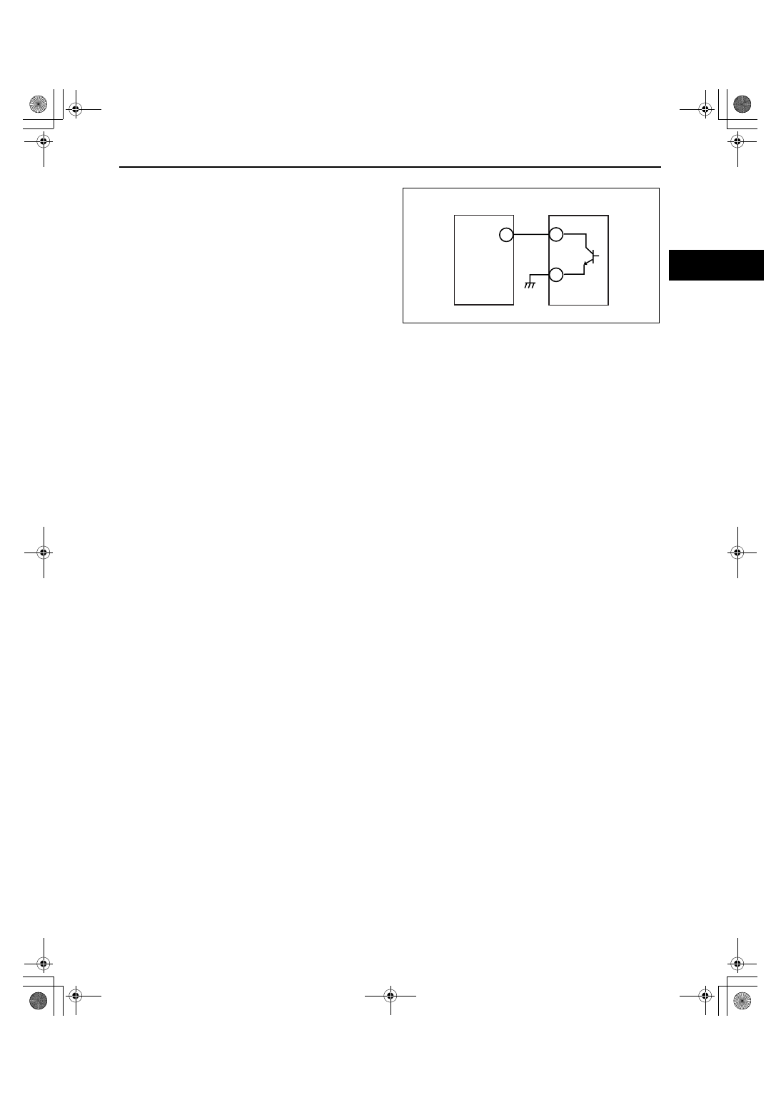
PCM
INPUT
1
3
2
acxuuw00002367
1871-1U-06B(01-03).fm 81 ページ 2006年3月15日 水曜日 午前10時36分