Mazda CX 7. Manual - part 74
ON-BOARD DIAGNOSTIC [L3 WITH TC]
01-02–251
01-02
End Of Sie
WM: DTC P25XX
DTC P2502[L3 WITH TC]
id010239814000
Diagnostic procedure
DTC P2502
Charging system voltage problem
DETECTION
CONDITION
• PCM determines that the generator output voltage is above 17 V or the battery voltage is below 11 V while
the engine is running.
Diagnostic support note
• This is a continuous monitor (Other).
• The MIL does not illuminate.
• FREEZE FRAME DATA is not available.
• DTCs are stored in the PCM memory.
POSSIBLE
CAUSE
• Open circuit between generator terminal B and battery positive terminal
• Battery malfunction
• Generator malfunction
• PCM is poorly connected
• PCM, generator and/or battery are poorly connected
STEP
INSPECTION
ACTION
1
VERIFY FREEZE FRAME DATA HAS BEEN
RECORDED
• Has the FREEZE FRAME DATA been
recorded?
Yes
Go to the next step.
No
Record the FREEZE FRAME DATA on the repair order,
then go to the next step.
2
VERIFY RELATED REPAIR INFORMATION
AVAILABILITY
• Verify related Service Bulletins and/or on-line
repair information availability.
• Is any related repair information available?
Yes
Perform the repair or diagnosis according to the available
repair information.
• If the vehicle is not repaired, go to the next step.
No
Go to the next step.
2BE 2BA 2AW 2AS 2AO 2AK 2AG 2AC 2Y 2U 2Q 2M
2E
2A
2I
2BH 2BD 2AZ 2AV 2AR 2AN 2AJ 2AF 2AB 2X 2T 2P
2H
2D
2L
2BG 2BC 2AY 2AU 2AQ 2AM 2AI 2AE 2AA 2W 2S 2O
2G
2C
2K
2BF 2BB 2AX 2AT 2AP 2AL 2AH 2AD 2Z
2V 2R 2N
2F
2B
2J
1BE 1BA 1AW 1AS 1AO 1AK 1AG 1AC 1Y 1U 1Q 1M
1E
1A
1I
1BH 1BD 1AZ 1AV 1AR 1AN 1AJ 1AF 1AB 1X
1T
1P
1H
1D
1L
1BG 1BC 1AY 1AU 1AQ 1AM 1AI 1AE 1AA 1W 1S 1O
1G
1C
1K
1BF 1BB 1AX 1AT 1AP 1AL 1AH 1AD 1Z
1V
1R 1N
1F
1B
1J
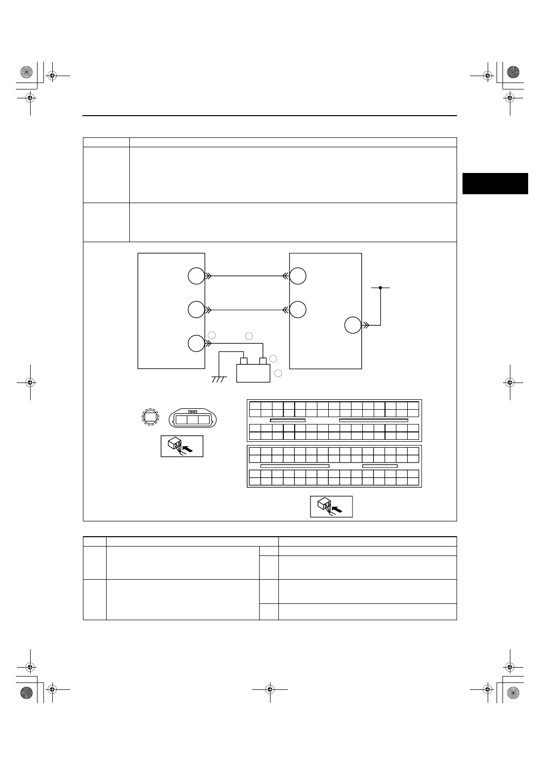
+
-
GENERATOR
D
P
B
2AI
2AJ
PCM
BATTERY
P
B
D
PCM
WIRING HARNESS-SIDE CONNECTOR
GENERATOR
WIRING HARNESS-SIDE CONNECTOR
1BE
MAIN RELAY
6
5
3
4
*
1871-1U-06B(01-02).fm 251 ページ 2006年3月15日 水曜日 午前10時32分