Mazda CX 7. Manual - part 68
ON-BOARD DIAGNOSTIC [L3 WITH TC]
01-02–227
01-02
3
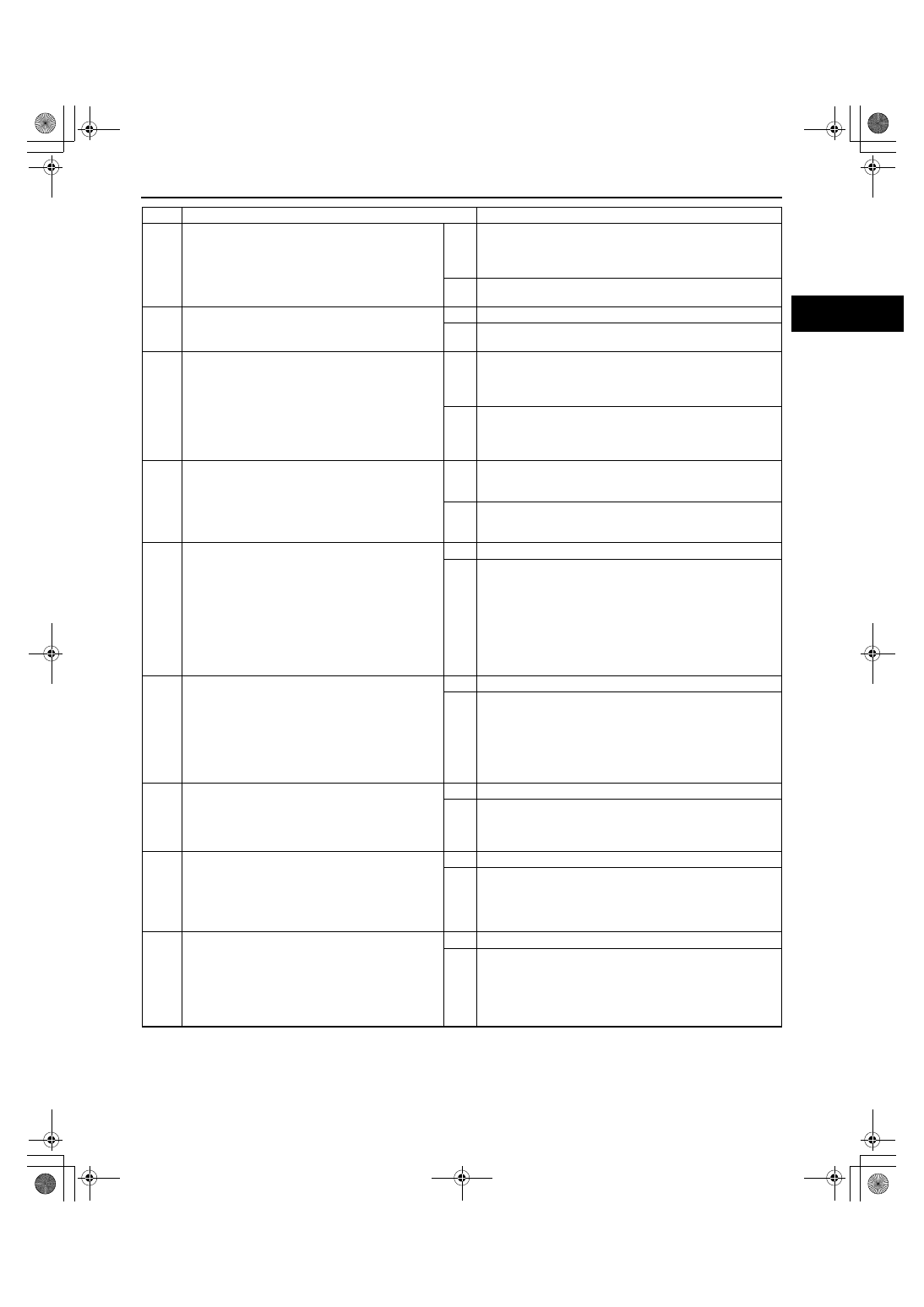
VERIFY RELATED PENDING CODE OR
STORED DTCS
• Turn the ignition switch to off, then to the ON
position (Engine off).
• Verify related pending code or stored DTCs.
• Are other DTCs present?
Yes
If misfire the DTC is present, go to Step 8.
If other DTCs is present, go to the applicable DTC
inspection.
(See01-02-13 DTC TABLE[L3 WITH TC].)
No
If driveability concern is present, go to Step 8.
If not, go to the next step.
4
IDENTIFY TRIGGER DTC FOR FREEZE FRAME
DATA
• Is DTC P2178 on FREEZE FRAME DATA?
Yes
Go to the next step.
No
Go to troubleshooting procedures for DTC on FREEZE
FRAME DATA.
5
VERIFY CURRENT INPUT SIGNAL STATUS
(IGNITION SWITCH TO THE ON POSITION/
IDLE)
• Access the APP1, APP2, ECT, MAF, TP and
VSS PIDs using the M-MDS.
• Is there any signal that is far out of specification
when the ignition switch is at the ON position
and engine runs?
Yes
Inspect the sensor and excessive resistance in related
wiring harnesses.
Repair or if necessary.
Then go to Step 19.
No
Go to the next step.
6
VERIFY CURRENT INPUT SIGNAL STATUS
UNDER TROUBLE CONDITION
• Inspect the same PIDs as Step 5 while
simulating FREEZE FRAME DATA condition.
• Is there any signal which causes drastic
changes?
Yes
Inspect the sensor and related wiring harnesses, repair or
replace it.
Then go to Step 19.
No
Go to the next step.
7
VERIFY CURRENT INPUT SIGNAL STATUS OF
FRONT HO2S
• Access the O2S11 for P2177 PID using the M-
MDS.
• Check the PID under following accelerator
pedal condition in NEUTRAL.
• Is the PID reading normal?
— –0.1— 0.1 A when idle
— Below 0.25 mA just after release of
accelerator pedal (lean condition)
Yes
Go to the next step.
No
Visually inspect for any gas leakage between the exhaust
manifold and the front HO2S.
Then go to Step 19.
8
VERIFY CURRENT INPUT SIGNAL STATUS OF
MAF SENSOR
• Connect the M-MDS to the DLC-2.
• Start the engine.
• Access the MAF PID.
• Verify that the MAF PID changes quickly
according to engine speed.
• Is the PID normal?
Yes
Go to the next step.
No
Replace the MAF/IAT sensor, then go to Step 19.
9
INSPECT PURGE SOLENOID OPERATION
• Perform the Purge Control System Inspection.
(See01-03-78 ENGINE CONTROL SYSTEM
OPERATION INSPECTION[L3 WITH TC].)
• Does the purge control system work properly?
Yes
Go to the next step.
No
Repair or replace the malfunctioning part according to
inspection result, then go to Step 19.
10
INSPECT PCV VALVE OPERATION
• Inspect the PCV valve operation.
(See01-16-14 POSITIVE CRANKCASE
VENTILATION (PCV) VALVE INSPECTION[L3
WITH TC].)
• Is the PCV valve normal?
Yes
Go to the next step.
No
Replace the PCV valve, then go to Step 19.
11
INSPECT VARIABLE SWIRL CONTROL
OPERATION
• Perform the Variable Swirl Control Operation
Inspection.
(See01-03-78 ENGINE CONTROL SYSTEM
OPERATION INSPECTION[L3 WITH TC].)
• Does the variable swirl control work properly?
Yes
Go to the next step.
No
Repair or replace the malfunctioning part according to
inspection result, then go to Step 19.
STEP
INSPECTION
ACTION
1871-1U-06B(01-02).fm 227 ページ 2006年3月15日 水曜日 午前10時32分