Mazda CX 7. Manual - part 26
ON-BOARD DIAGNOSTIC [L3 WITH TC]
01-02–59
01-02
DTC P0112[L3 WITH TC]
id010239803700
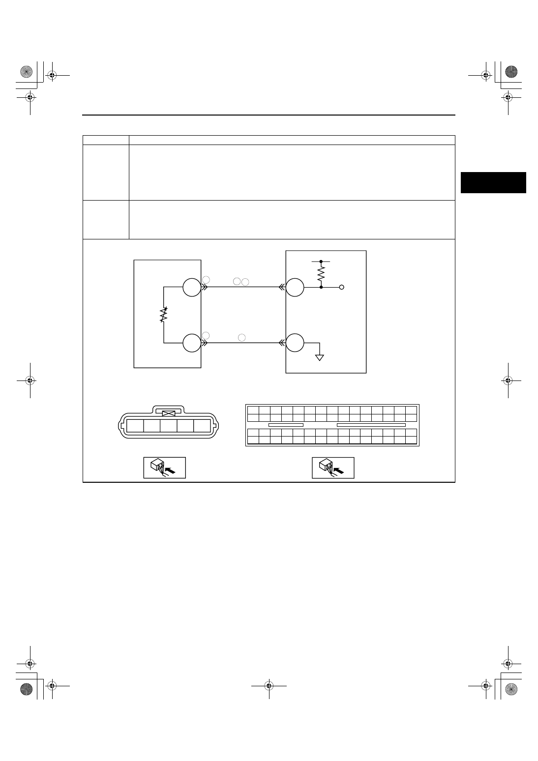
DTC P0112
IAT circuit low input
DETECTION
CONDITION
• The PCM monitors the IAT sensor signal. If the PCM detects on IAT sensor voltage below 0.06 V, the PCM
determines that the IAT sensor circuit has a malfunction.
Diagnostic support note
• This is a continuous monitor (CCM).
• MIL illuminates if the PCM detects the above malfunction condition during the first drive cycle.
• FREEZE FRAME DATA is available.
• DTCs are stored in the PCM memory.
POSSIBLE
CAUSE
• IAT sensor malfunction
• Poor connection at the MAF/IAT sensor or PCM connector
• Short to ground between MAF/IAT sensor terminal D and PCM terminal 1M
• Short to each harness IAT signal circuit and IAT ground circuit.
• PCM malfunction
D
E
1AR
1M
PCM
PCM
HARNESS SIDE CONNECTOR
MAF/IAT SENSOR
HARNESS SIDE CONNECTOR
A
B
C
D
E
IAT SENSOR
5
3
3
6
6
1BE 1BA 1AW 1AS 1AO 1AK 1AG 1AC 1Y 1U 1Q 1M
1E
1A
1I
1BH 1BD 1AZ 1AV 1AR 1AN 1AJ 1AF 1AB 1X
1T
1P
1H
1D
1L
1BG 1BC 1AY 1AU 1AQ 1AM 1AI 1AE 1AA 1W 1S 1O
1G
1C
1K
1BF 1BB 1AX 1AT 1AP 1AL 1AH 1AD 1Z
1V
1R 1N
1F
1B
1J
1871-1U-06B(01-02).fm 59 ページ 2006年3月15日 水曜日 午前10時32分