Mazda CX 7. Manual - part 19
ON-BOARD DIAGNOSTIC [L3 WITH TC]
01-02–31
01-02
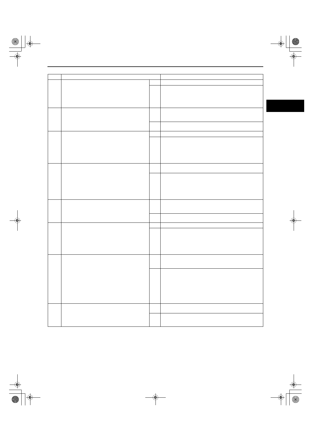
Diagnostic procedure
End Of Sie
STEP
INSPECTION
ACTION
1
VERIFY FREEZE FRAME DATA AND
DIAGNOSTIC MONITORING TEST RESULTS
HAVE BEEN RECORDED
• Have the FREEZE FRAME DATA and
DIAGNOSTIC MONITORING TEST RESULTS
(HO2S heater related) been recorded?
Yes
Go to the next step.
No
Record the FREEZE FRAME DATA and DIAGNOSTIC
MONITORING TEST RESULTS on the repair order, then
go to the next step.
2
VERIFY RELATED REPAIR INFORMATION
AVAILABILITY
• Verify related Service Bulletins and/or on-line
repair information availability.
• Is any related repair information available?
Yes
Perform the repair or diagnosis according to the available
repair information.
• If the vehicle is not repaired, go to the next step.
No
Go to the next step.
3
INSPECT FRONT HO2S CONNECTOR FOR
POOR CONNECTION
• Turn the ignition switch off.
• Disconnect the front HO2S connector.
• Inspect for poor connection (such as damaged/
pulled-out pins, and corrosion).
• Is there any malfunction?
Yes
Repair or replace the terminal, then go to Step 7.
No
Go to the next step.
4
INSPECT FRONT HO2S HEATER CONTROL
CIRCUIT FOR SHORT TO POWER SUPPLY
• Turn the ignition switch to the ON position
(Engine off).
• Measure the voltage between front HO2S
terminal 2D (wiring harness-side) and body
ground.
• Is the voltage B+?
Yes
Repair or replace the wiring harness for a possible short to
power supply, then go to Step 7.
No
Go to the next step.
5
INSPECT FRONT HO2S HEATER
• Inspect the front HO2S heater.
(See01-40-37 HEATED OXYGEN SENSOR
(HO2S) INSPECTION[L3 WITH TC].)
• Is there any malfunction?
Yes
Replace the front HO2S, then go to Step 7.
(See01-15-2 EXHAUST SYSTEM REMOVAL/
INSTALLATION[L3 WITH TC].)
No
Go to the next step.
6
INSPECT PCM CONNECTOR FOR POOR
CONNECTION
• Turn the ignition switch off.
• Disconnect the PCM connector.
• Inspect for poor connection (such as damaged/
pulled-out pins, and corrosion).
• Is there any malfunction?
Yes
Repair or replace the terminal, then go to the next step.
No
Go to the next step.
7
VERIFY TROUBLESHOOTING OF DTC P0032
COMPLETED
• Make sure to reconnect all disconnected
connectors.
• Clear the DTC from the PCM memory using
the M-MDS.
• Perform the HO2S heater, HO2S, and TWC
Repair Verification Drive Mode.
(See01-02-10 OBD-II DRIVE MODE[L3 WITH
TC].)
• Is the PENDING CODE for this DTC present?
Yes
Replace the PCM, then go to the next step.
(See01-40-6 PCM REMOVAL/INSTALLATION[L3 WITH
TC].)
No
Go to the next step.
8
VERIFY AFTER REPAIR PROCEDURE
• Perform the “AFTER REPAIR PROCEDURE”.
(See01-02-10 AFTER REPAIR
PROCEDURE[L3 WITH TC].)
• Are any DTCs present?
Yes
Go to the applicable DTC inspection.
(See01-02-13 DTC TABLE[L3 WITH TC].)
No
DTC troubleshooting completed.
1871-1U-06B(01-02).fm 31 ページ 2006年3月15日 水曜日 午前10時32分