Mazda CX 7. Manual - part 6


  Index      Mazda     Mazda CX 7 - service repair manual 2007 year


Search            


Content   ..  4  5  6  7   ..


Mazda CX 7. Manual - part 6


GENERAL INFORMATION 

00-00–19

00-00

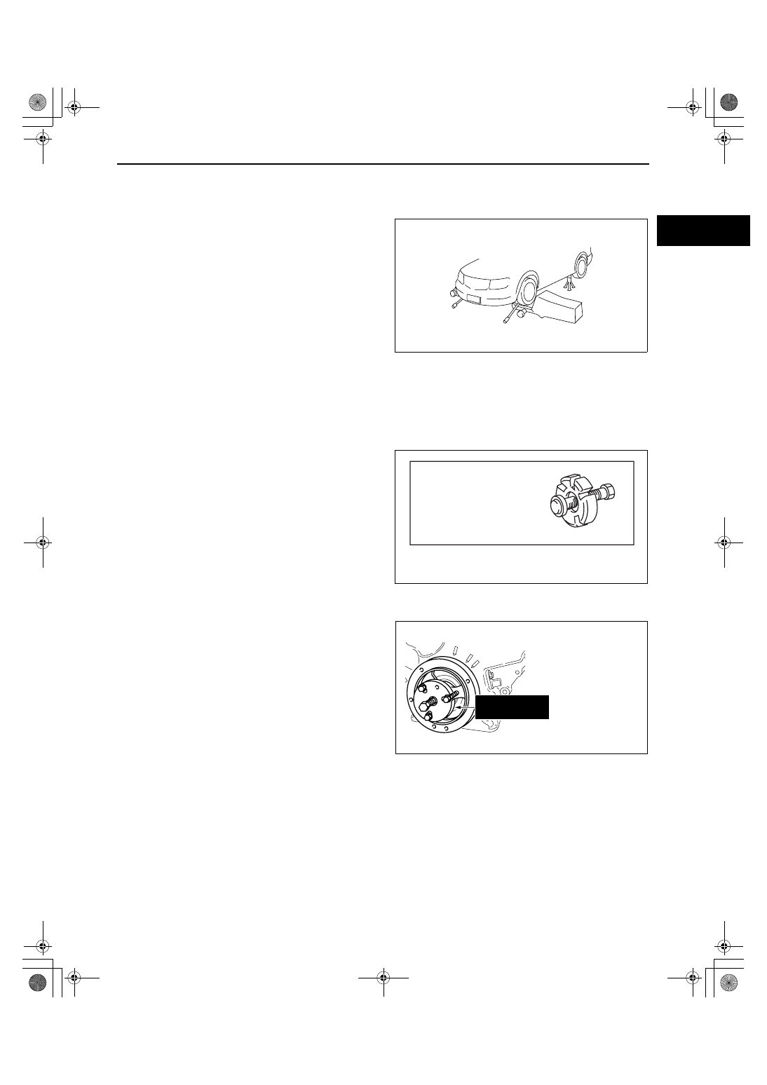
Wheel balancer (on the vehicle balancer)

1. Jack up all four wheels.
2. Support the wheels (front or rear) on the side to be measured (near the wheels) using a wheel balancer sensor 

stand.

3. Support the wheels on the side not to be 

measured (near the wheels) using safety stands.

4. Set up the wheel balancer and rotate the wheels 

using engine drive to measure the wheel balance.

SST

• Some global SST or equivalent are used as SSTs necessary for vehicle repair. Note that these SSTs are 

marked with global SST numbers.

• Note that a global SST number is written together with a corresponding Mazda SST number as shown below.

Example (section **-60)

Example (Except section **-60)

End Of Sie

acxuuw00000330

1: Mazda SST number

2: Global SST number 

Crankshaft Damper Remover

1: 49 UN303 009
2: 303-009

acxuuw00000021

—Global SST Number
—Mazda SST Number

(49 UN30 3009)

303—009

acxuuw00000022

GENERAL INFORMATION 

00-00–20

INSTALLATION OF RADIO SYSTEM

id000000800300

• If a radio system is installed improperly or if a high-powered type system is used, the CIS and other systems 

may be affected. When the vehicle is to be equipped with a radio, observe the following precautions:

— Install the antenna at the farthest point from control modules.

— Install the antenna feeder as far as possible from the control module wiring harnesses.

— Ensure that the antenna and feeder are properly adjusted.

— Do not install a high-powered radio system.

End Of Sie

ELECTRICAL SYSTEM

id000000800400

Electrical Parts
Battery cable

• Before disconnecting connectors or removing 

electrical parts, disconnect the negative battery 
cable.

Wiring Harness

• To remove the wiring harness from the clip in the 

engine room, pry up the hook of the clip using a 
flathead screwdriver.

Caution

• Do not remove the wiring harness 

protective tape. Otherwise, the wires 
could rub against the body, which could 
result in water penetration and electrical 
shorting.

BATTERY CABLE

acxuuw00000451

acxuuw00000452

NO GOOD

acxuuw00000453

GENERAL INFORMATION 

00-00–21

00-00

Connectors
Disconnecting connectors

• When disconnecting a connector, grasp the 

connectors, not the wires.

• Connectors can be disconnected by pressing or 

pulling the lock lever as shown.

Locking connector

• When locking connectors, listen for a click 

indicating they are securely locked.

GOOD

NO GOOD

acxuuw00000454

acxuuw00000455

acxuuw00000456

GENERAL INFORMATION 

00-00–22

Inspection

Caution

• To prevent damage to the terminal, wrap a thin wire around the tester probe before inserting into 

terminal.

• When a tester is used to inspect for continuity or 

measuring voltage, insert the tester probe from 
the wiring harness side.

• Inspect the terminals of waterproof connectors 

from the connector side since they cannot be 
accessed from the wiring harness side.

Terminals
Inspection

• Pull lightly on individual wires to verify that they 

are secured in the terminal.

GOOD

NO GOOD

acxuuw00000457

GOOD

NO GOOD

acxuuw00000458

acxuuw00000459


Content   ..  4  5  6  7   ..