Mazda CX 7. Manual - part 2


  Index      Mazda     Mazda CX 7 - service repair manual 2007 year


Search            


Content   ..  1  2  3   ..


Mazda CX 7. Manual - part 2


GENERAL INFORMATION 

00-00–3

00-00

HOW TO USE THIS MANUAL

id000000800100

Range of Topics

• This manual contains procedures for performing all required service operations. The procedures are divided 

into the following five basic operations:

— Removal/Installation

— Disassembly/Assembly

— Replacement

— Inspection

— Adjustment

• Simple operations which can be performed easily just by looking at the vehicle (i.e., removal/installation of 

parts, jacking, vehicle lifting, cleaning of parts, and visual inspection) have been omitted.

Service Procedure
Inspection, adjustment

• Inspection and adjustment procedures are 

divided into steps. Important points regarding the 
location and contents of the procedures are 
explained in detail and shown in the illustrations.
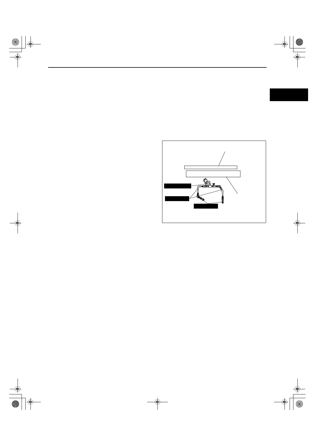
49 H002 671

49 H032 322

49 1232 670A

SHOWS PROCEDURE ORDER
FOR SERVICE

Fluid Pressure Inspection

1. Assemble the SSTs as shown in the figure.

Tightening torque

SHOWS TIGHTENING
TORQUE
SPECIFICATIONS

Caution

Connect the gauge set from under
the vehicle to prevent contact with
the drive belt and the cooling fan.

39—49 N·m {4.0—5.0 kgf·m, 29—36 ft·lbf}

acxuuw00000434

GENERAL INFORMATION 

00-00–4

Repair procedure

1. Most repair operations begin with an overview illustration. It identifies the components, shows how the parts fit 

together, and describes visual part inspection. However, only removal/installation procedures that need to be 
performed methodically have written instructions.

2. Expendable parts, tightening torques, and symbols for oil, grease, and sealant are shown in the overview 

illustration. In addition, symbols indicating parts requiring the use of special service tools or equivalent are also 
shown.

3. Procedure steps are numbered and the part that is the main point of that procedure is shown in the illustration 

with the corresponding number. Occasionally, there are important points or additional information concerning a 
procedure. Refer to this information when servicing the related part.

GREASEGREASE

GREASEGREASE

INDICATES RELEVANT
REFERENCES THAT  NEED
TO BE FOLLOWED DURING
INSTALLATION

SHOWS SPECIAL
SERVICE TOOL  (SST)
FOR SERVICE OPERATION

SHOWS SPECIAL
SERVICE TOOL  (SST)
NO.

SHOWS TIGHTENING
TORQUE
SPECIFICATIONS

SHOWS PROCEDURE ORDER
FOR SERVICE

SHOWS APPLICATION
POINTS OF GREASE, ETC.

SHOWS EXPENDABLE PARTS

SHOWS DETAILS

SHOWS TIGHTENING
TORQUE UNITS

KNUCKLE

UPPER TRAILING LINK

LOWER TRAILING LINK

SST

SST

SST

SST

R

R

R

R

9

2

1

4

5

3

6

1

2

8

7

12

10

11

N·m {kgf·m, ft·lbf}

118—156 {12.0—16.0, 87—115}

94—116 {9.5—11.9, 69—86}

44—60 {4.4—6.2, 32—44}

43—56 {4.3—5.8, 32—41}

49 T028  304

49 T028  305

49 T028  303

Procedure

"Removal/Installation"
Portion

"Inspection After
  Installation" Portion

INSTALL THE PARTS BY
PERFORMING STEPS
1    3 IN REVERSE ORDER

SHOWS  REFERRAL
NOTES FOR SERVICE

SHOWS REFERRAL
NOTES FOR
SERVICE

LOWER TRAILING LINK, UPPER TRAILING LINK REMOVAL/INSTALLATION                            

1. Jack up the rear of the vehicle and support it with safety stands.

2. Remove the undercover. (See 01-10-4 Undercover Removal)
3. Remove in the order indicated in the table.
4. Install in the reverse order of removal.
5. Inspect the rear wheel alignment and adjust it if necessary.

SHOWS SERVICE
ITEM (S)

1

Split pin

2

Nut

3

Lower trailing link ball joint

4

(See 02-14-5 Lower Trailing Link Ball Joint Removal Note)

Bolt

5

Lower trailing link 

6

Dust boot (lower trailing link) 

7

Split pin

8

Nut

9

Upper trailing link ball joint

(See 02-14-5 Upper Trailing Link Ball Joint Removal Note)

10

Nut

11

Upper trailing link

12

Dust boot (upper trailing link)

Lower Trailing Link Ball Joint, Upper Trailing Link
Ball Joint Removal Note

Remove the ball joint using the SSTs.

acxuuw00000435

GENERAL INFORMATION 

00-00–5

00-00

Symbols

• There are eight symbols indicating oil, grease, fluids, sealant, and the use of SST or equivalent. use. These 

symbols show application points or use of these materials during service.

Advisory Messages

• You will find several Warnings, Cautions, Notes, Specifications and Upper and Lower Limits in this 

manual.

Warning

• A Warning indicates a situation in which serious injury or death could result if the warning is ignored.

Caution

• A Caution indicates a situation in which damage to the vehicle or parts could result if the caution is ignored.

Note

• A Note provides added information that will help you to complete a particular procedure.

Specification

• The values indicate the allowable range when performing inspections or adjustments.

Upper and lower limits

• The values indicate the upper and lower limits that must not be exceeded when performing inspections or 

adjustments.

Symbol

Meaning

Kind

Apply oil

New appropriate 
engine oil or gear 
oil

Apply brake fluid

New appropriate 
brake fluid

Apply automatic 
transaxle/
transmission fluid

New appropriate 
automatic
transaxle/
transmission fluid

Apply grease

Appropriate 
grease

Apply sealant

Appropriate
sealant

Apply petroleum 
jelly

Appropriate
petroleum jelly

Replace part

O-ring, gasket, 
etc.

Use SST or
equivalent

Appropriate tools

OIL

BRAKE
FLUID

A

ATF

TF

GREASEGREASE

SEALANT

P

R

SST

GENERAL INFORMATION 

00-00–6

Troubleshooting Procedure
Basic flow of troubleshooting

DTC troubleshooting flow (on-board diagnostic)

• Diagnostic trouble codes (DTCs) are important hints for repairing malfunctions that are difficult to simulate. 

Perform the specific DTC diagnostic inspection to quickly and accurately diagnose the malfunction.

• The on-board diagnostic function is used during inspection. When a DTC is shown specifying the cause of a 

malfunction, continue the diagnostic inspection according to the items indicated by the on-board diagnostic 
function.

Diagnostic index

• The diagnostic index lists the symptoms of specific malfunctions. Select the symptoms related or most closely 

relating to the malfunction.

Quick diagnosis chart (If mentioned)

• The quick diagnosis chart lists diagnosis and inspection procedures to be performed specifically relating to the 

cause of the malfunction.

Symptom troubleshooting

• Symptom troubleshooting quickly determines the location of the malfunction according to symptom type.

CUSTOMER ARRIVES

DTC TABLE

DTC

NO WARNING LIGHT*
WITH SYMPTOM

CHECK DTC

IGNITION ON TEST, IDLING
TEST

WITHOUT DTC

DIAGNOSE BY SYMPTOM
(SYMPTOM TROUBLESHOOTING)
1. DIAGNOSTIC INDEX
2. QUICK DIAGNOSIS CHART 

(IF MENTIONED)

3. SYMPTOM 

TROUBLESHOOTING 

*: INDICATOR LIGHTS AND WARNING 

LIGHTS THAT INDICATE MALFUNCTIONS

DTC 
TROUBLESHOOTING 
FLOW

DIAGNOSE BY DTC 
(ON-BOARD DIAGNOSTIC)

WARNING LIGHT* 
ON/FLASHING

CHECK FOR 
PRIORITIZED DTC

acxuuw00000444


Content   ..  1  2  3   ..