Mazda Protege 5. Manual - part 332


  Index      Mazda     Mazda Protege 5 - service repair manual 2002 year


Search            


Content   ..  330  331  332  333   ..


Mazda Protege 5. Manual - part 332


EXTERIOR TRIM 

09–16–7

09–16

Rear Carrier Bar Installation Note

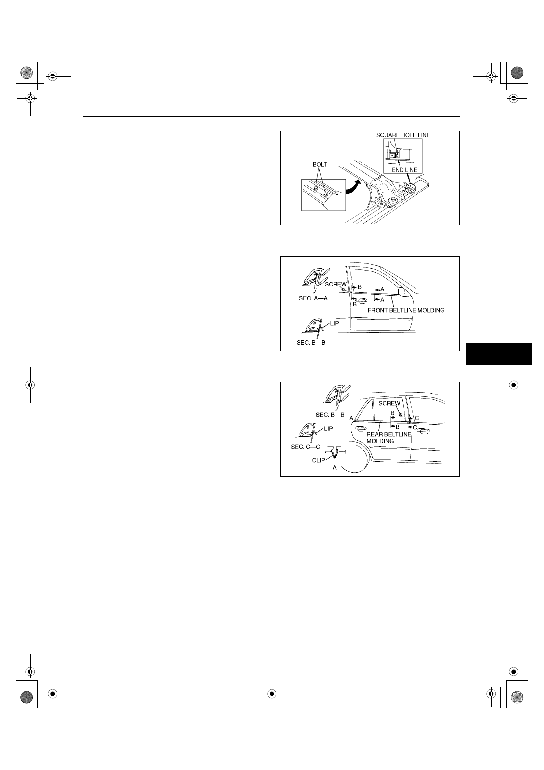
1. Loosen the bolt under the rear carrier bar, and 

adjust the rear carrier bar position.

2. When the rear carrier bar is in the final position, 

align the square hole line for cover B with the rear 
cover line.

End Of Sie

FRONT BELTLINE MOLDING REMOVAL/INSTALLATION

A3U091650640W01

1. Open the front door glass fully.
2. Remove the screw.
3. Pull the front beltline molding up, then remove it.
4. Install in the reverse order of removal.

End Of Sie

REAR BELTLINE MOLDING REMOVAL/INSTALLATION

A3U091650660W01

1. Remove the rear door glass. (See 09–11–5 REAR DOOR DISASSEMBLY/ASSEMBLY.)
2. Remove the screw.
3. Pull the rear beltline molding up, then disengage 

clip A.

4. Install in the reverse order of removal.

End Of Sie

REAR WINDOW GLASS MOLDING REMOVAL

A3U091650690W01

Note

Rear window glass molding is a replacement part.

1. Remove the rear window glass. (See 09–12–11 REAR WINDOW GLASS REMOVAL.)
2. Remove the rear window glass molding from the rear window glass.

End Of Sie

REAR WINDOW GLASS MOLDING INSTALLATION

A3U091650690W02

Note

Rear window glass molding is a replacement part.

1. Install the rear window glass molding to the rear window glass. (See 09–12–14 REAR WINDOW GLASS 

INSTALLATION.)

End Of Sie

A3U0916W012

X3U916WA9

X3U916WAA

1712-1U-01G(09-16).fm  7 ページ  2001年6月29日 金曜日 午前10時34分

EXTERIOR TRIM 

09–16–8

WINDSHIELD MOLDING REMOVAL

A3U091650600W01

Note

Windshield molding is a replacement part.

1. Remove the windshield. (See 09–12–19 WINDSHIELD REMOVAL.)
2. Remove the windshield molding from the windshield.

End Of Sie

WINDSHIELD MOLDING INSTALLATION

A3U091650600W02

Note

Windshield molding is a replacement part.

1. Install the windshield molding to the windshield. (See 09–12–21 WINDSHIELD INSTALLATION.)

End Of Sie

ROOF MOLDING REMOVAL/INSTALLATION

A3U091650620W01

1. Pull the front edge and rear edge of the roof 

molding up (1).

2. Slide the roof molding rearward, then remove it 

(2).

3. Install in the reverse order of removal.

End Of Sie

REAR SPOILER REMOVAL/INSTALLATION

A3U091651950W01

4SD

1. Disconnect the negative battery cable.
2. Disconnect the high-mount brake light connector.
3. Remove the bolts.
4. Pull the rear spoiler upward, then remove it.
5. Install in the reverse order of removal.

X3U916WAB

Y3U916WA0

1712-1U-01G(09-16).fm  8 ページ  2001年6月29日 金曜日 午前10時34分

EXTERIOR TRIM 

09–16–9

09–16

5HB

1. Disconnect the negative battery cable.
2. Remove the hole cover A using a tape-wrapped screwdriver.
3. Remove the fasteners, then remove hole cover B.
4. Pull out the high-mount brake light connector, 

then disconnect it.

5. Remove the bolts and nuts.
6. Pull the rear spoiler upward, then disengage clips 

A from the body.

7. Install in the reverse order of removal.

End Of Sie

A3U0916W006

A3U0916W007

1712-1U-01G(09-16).fm  9 ページ  2001年6月29日 金曜日 午前10時34分

INTERIOR TRIM 

09–17–1

09–17

09–17

INTERIOR TRIM

DASHBOARD 

REMOVAL/INSTALLATION . . . . . . . . .  09–17–1

DASHBOARD 

DISASSEMBLY/ASSEMBLY  . . . . . . . .  09–17–3

VENTILATOR GRILLE 

REMOVAL/INSTALLATION . . . . . . . . .  09–17–3

Center Side  . . . . . . . . . . . . . . . . . . . . .  09–17–3
Driver’s side . . . . . . . . . . . . . . . . . . . . .  09–17–4
Passenger’s side . . . . . . . . . . . . . . . . .  09–17–4

CENTER PANEL 

REMOVAL/INSTALLATION . . . . . . . . .  09–17–4

COLUMN COVER 

REMOVAL/INSTALLATION . . . . . . . . .  09–17–5

CONSOLE ADJUSTMENT . . . . . . . . . . .  09–17–5
CONSOLE REMOVAL/INSTALLATION .  09–17–5

Boot Panel Removal Note . . . . . . . . . .  09–17–6
Console Cover Removal Note . . . . . . .  09–17–6

CONSOLE DISASSEMBLY/ASSEMBLY 09–17–6
GLOVE COMPARTMENT 

REMOVAL/INSTALLATION . . . . . . . . .  09–17–7

LOWER PANEL 

REMOVAL/INSTALLATION . . . . . . . . .  09–17–7

Driver’s side . . . . . . . . . . . . . . . . . . . . .  09–17–7
Passenger’s side . . . . . . . . . . . . . . . . .  09–17–7

METER HOOD 

REMOVAL/INSTALLATION . . . . . . . . .  09–17–8

SIDE PANEL 

REMOVAL/INSTALLATION . . . . . . . . .  09–17–8

SIDE WALL REMOVAL/INSTALLATION 09–17–8
FRONT DOOR TRIM 

REMOVAL/INSTALLATION . . . . . . . . .  09–17–9

REAR DOOR TRIM 

REMOVAL/INSTALLATION . . . . . . . . .  09–17–9

A-PILLAR TRIM 

REMOVAL/INSTALLATION . . . . . . . . .  09–17–10

B-PILLAR LOWER TRIM REMOVAL . . .  09–17–10

B-PILLAR LOWER TRIM 

INSTALLATION  . . . . . . . . . . . . . . . . . . . 09–17–11

B-PILLAR UPPER TRIM 

REMOVAL/INSTALLATION . . . . . . . . . . 09–17–11

C-PILLAR TRIM 

REMOVAL/INSTALLATION . . . . . . . . . . 09–17–11

4SD . . . . . . . . . . . . . . . . . . . . . . . . . . . . 09–17–11
5HB   . . . . . . . . . . . . . . . . . . . . . . . . . . . 09–17–12

REAR PACKAGE TRIM 

REMOVAL/INSTALLATION . . . . . . . . . . 09–17–12

4SD . . . . . . . . . . . . . . . . . . . . . . . . . . . . 09–17–12
5HB . . . . . . . . . . . . . . . . . . . . . . . . . . . . 09–17–12

FRONT SCUFF PLATE 

REMOVAL/INSTALLATION . . . . . . . . . . 09–17–13

REAR SCUFF PLATE 

REMOVAL/INSTALLATION . . . . . . . . . . 09–17–13

FRONT SIDE TRIM 

REMOVAL/INSTALLATION . . . . . . . . . . 09–17–13

TIRE HOUSE TRIM 

REMOVAL/INSTALLATION . . . . . . . . . . 09–17–13

4SD . . . . . . . . . . . . . . . . . . . . . . . . . . . . 09–17–13
5HB   . . . . . . . . . . . . . . . . . . . . . . . . . . . 09–17–14

TRUNK END TRIM 

REMOVAL/INSTALLATION . . . . . . . . . . 09–17–14

TRUNK SIDE TRIM 

REMOVAL/INSTALLATION . . . . . . . . . . 09–17–15

4SD . . . . . . . . . . . . . . . . . . . . . . . . . . . . 09–17–15
5HB . . . . . . . . . . . . . . . . . . . . . . . . . . . . 09–17–15

TRUNK SIDE UPPER TRIM 

REMOVAL/INSTALLATION . . . . . . . . . . 09–17–15

LIFTGATE TRIM 

REMOVAL/INSTALLATION . . . . . . . . . . 09–17–16

HEADLINER 

REMOVAL/INSTALLATION . . . . . . . . . . 09–17–16

FLOOR COVERING 

REMOVAL/INSTALLATION . . . . . . . . . . 09–17–17

End of Toc

DASHBOARD REMOVAL/INSTALLATION

A3U091755100W01

1. Remove the passenger-side air bag module if equipped. (See 08–10–6 PASSENGER-SIDE AIR BAG 

MODULE REMOVAL/INSTALLATION.)

2. Remove the combination switch. (See 09–18–12 COMBINATION SWITCH REMOVAL/INSTALLATION.)
3. Remove the installation bolts then shift the assembled steering shaft in the dashboard. (See 06–12–6 

STEERING WHEEL AND COLUMN REMOVAL/INSTALLATION.)

4. Remove the instrument cluster. (See 09–22–3 INSTRUMENT CLUSTER REMOVAL/INSTALLATION.)
5. Remove the console. (See 09–17–5 CONSOLE REMOVAL/INSTALLATION.)
6. Remove the glove compartment.
7. Remove the lower panel.
8. Remove the hood release cable installation nut.
9. Remove the side wall.

10. Remove the A-pillar trim. (See 09–17–10 A-PILLAR TRIM REMOVAL/INSTALLATION.)
11. Remove the side panel.

1712-1U-01G(09-17).fm  1 ページ  2001年6月29日 金曜日 午前10時35分


Content   ..  330  331  332  333   ..