Mazda Protege 5. Manual - part 325


  Index      Mazda     Mazda Protege 5 - service repair manual 2002 year


Search            


Content   ..  323  324  325  326   ..


Mazda Protege 5. Manual - part 325


SECURITY AND LOCKS 

09–14–15

09–14

TRANSMITTER BATTERY INSPECTION

A3U091467543W01

Caution

••••

Since the battery voltage does not drop fully if the button is pushed for only 4 seconds or less, it 
cannot be properly examined to see whether it is good or bad. Always push the button for 5 
seconds.

Note

Since a correct measurement cannot be obtained if the battery temperature is low, make sure the battery 
has been at 18 

°°°°

C {64 

°°°°

F} or more for at least 30 minutes before reinspecting when a measurement 

value is under the standard voltage.

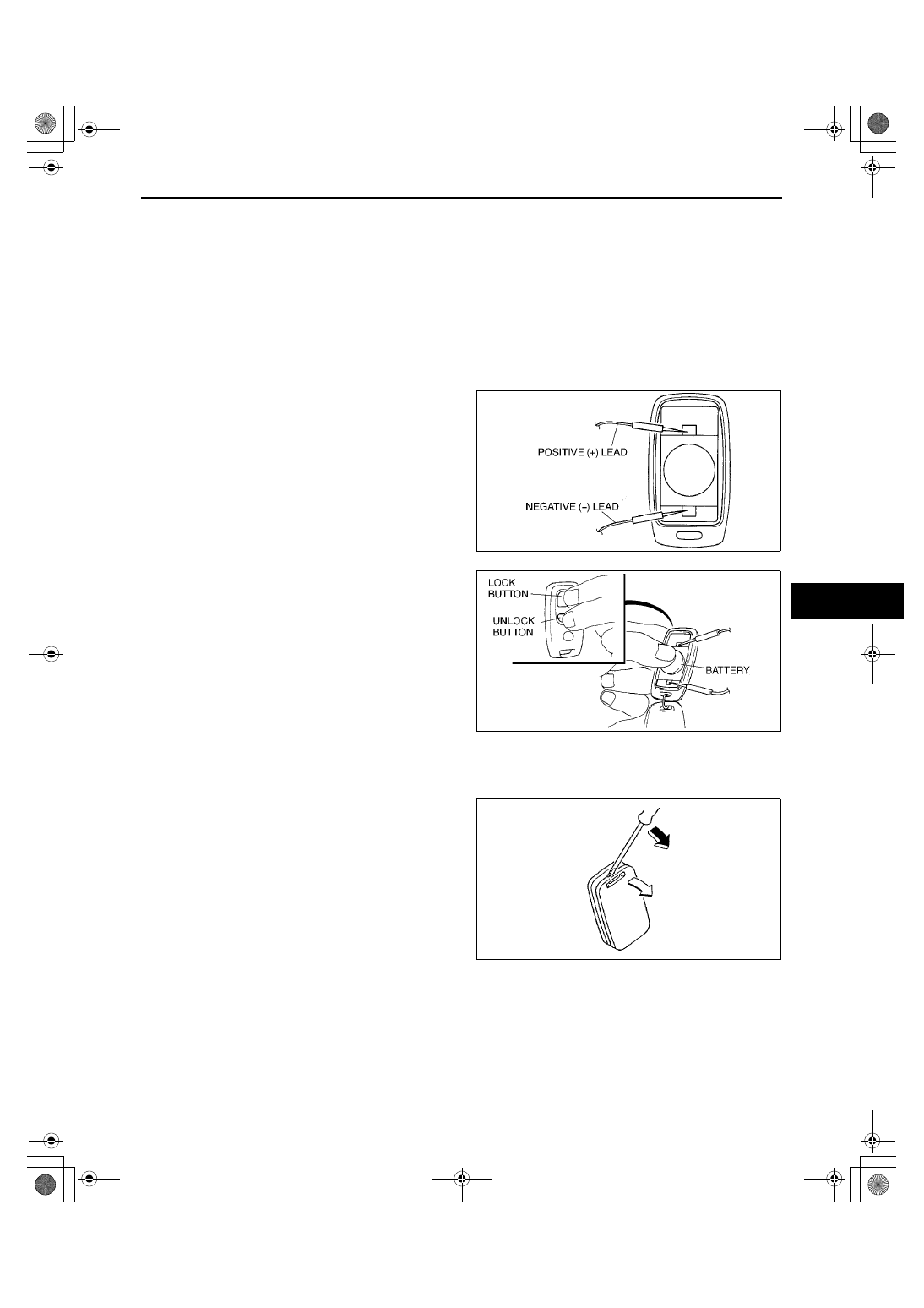
1. Remove the transmitter cover.
2. Apply the circuit tester leads to the positions as 

indicated in the figure.

3. While pressing the battery as shown in the figure, 

press the LOCK and UNLOCK buttons on the 
transmitter at the same time to start measurement 
of the voltage.

4. Release the buttons after 5 seconds.
5. Verify that the minimum voltage is the standard 

voltage or more for 10 seconds after starting 
measurement.

If the voltage is under the standard voltage, 
replace the battery.

Standard voltage

2.7 V

End Of Sie

TRANSMITTER BATTERY REPLACEMENT

A3U091467543W02

1. Insert a small flathead screwdriver into the slot 

and gently pry open the transmitter.

YDE7718W003

Z3U0914W006

YMU914WAS

1712-1U-01G(09-14).fm  15 ページ  2001年6月29日 金曜日 午前10時32分

SECURITY AND LOCKS 

09–14–16

2. Press the portion of the battery indicated by A and 

remove the battery.

3. Install a new battery (CR2025 or the equivalent) 

into the front portion of the holder with the positive 
pole (+) facing up. Press on the B portion of the 
battery to set the battery.

4. Align the front and back covers and snap the 

transmitter shut.

Battery specification

Lithium CR2025 

××××

 1

Note

The batteries will last about 2 years when 
used 10 times a day.

End Of Sie

FUEL-FILLER LID AND OPENER REMOVAL/INSTALLATION

A3U091456890W01

1. To remove the fuel-filler lid opener, remove the left side trunk side trim.
2. To remove the fuel-filler lid opener cable, perform the following.

(1) Remove the driver's seat. (See 09–13–1 FRONT SEAT REMOVAL/INSTALLATION.)
(2) Remove the driver-side front and rear scuff plate.
(3) Remove the driver-side B-pillar lower trim.
(4) Remove the driver's seat belt lower anchor.
(5) Remove the driver-side tire house trim.
(6) Remove the driver-side trunk side trim.
(7) Turn the floor covering over.

3. Install in the reverse order of removal.
4. Remove in the order indicated in the table.
5. Adjust the fuel-filler lid. (See 09–10–1 FUEL-FILLER LID ADJUSTMENT.)

.

YDE7718W001

YDE7718W002

A3U0914W001

1

Fuel-filler lid

2

Lift  spring

3

Fuel-filler lid opener

4

Cover

5

Fuel-filler lid opener lever

6

Fuel-filler lid opener cable

1712-1U-01G(09-14).fm  16 ページ  2001年6月29日 金曜日 午前10時32分

SECURITY AND LOCKS 

09–14–17

09–14

End Of Sie

HOOD LOCK AND OPENER REMOVAL/INSTALLATION

A3U091456620W01

1. Remove in the order indicated in the table.

2. Install in the reverse order of removal.

End Of Sie

TRUNK LID LOCK REMOVAL/INSTALLATION

A3U091456820W01

1. Disconnect the negative battery cable.
2. Remove in the order indicated in the table.

3. Install in the reverse order of removal.

Internal Trunk Lid Release Handle Installation Note

Caution

••••

Always keep the handle firmly attached to the holder and in the recessed position. Not securing 
the handle this way could allow it to snag luggage in the compartment and open the trunk lid.

1. After installation of the internal trunk lid release 

handle, pull the handle forward to verify the 
handle and rod are securely installed.

2. Attach the handle to the holder and in the 

recessed position.

End Of Sie

1

Hood lock

2

Hood release lever

3

Hood release cable

X3U914WB2

1

Cover

2

Connector

3

Trunk lid lock

4

Trunk lid lock cylinder

5

Internal trunk lid release handle
(See 09–14–17 Internal Trunk Lid Release Handle 
Installation Note.)

6

Rod

Z3U0914W008

Z3U0914W009

1712-1U-01G(09-14).fm  17 ページ  2001年6月29日 金曜日 午前10時32分

SECURITY AND LOCKS 

09–14–18

TRUNK LID OPENER REMOVAL/INSTALLATION

A3U091456822W01

1. To remove the trunk lid opener cable, perform the following.

(1) Remove the driver's seat. (See 09–13–1 FRONT SEAT REMOVAL/INSTALLATION.)
(2) Remove the driver-side front and rear scuff plate.
(3) Remove the driver-side B-pillar lower trim. (See 09–17–10 B-PILLAR LOWER TRIM REMOVAL.) (See 09–

17–11 B-PILLAR LOWER TRIM INSTALLATION.)

(4) Remove the driver's seat belt lower anchor.
(5) Remove the passenger’s side tire house trim. (See 09–17–13 TIRE HOUSE TRIM REMOVAL/

INSTALLATION.)

(6) Remove the trunk end trim. (See 09–17–14 TRUNK END TRIM REMOVAL/INSTALLATION.)
(7) Turn the floor covering over.

2. Remove in the order indicated in the table.

3. Install in the reverse order of removal.
4. Adjust the trunk lid opener cable. (See 09–14–18 

TRUNK LID OPENER CABLE ADJUSTMENT.)

End Of Sie

TRUNK LID OPENER CABLE ADJUSTMENT

A3U091456822W02

1. Install the trunk lid striker to one of the three 

places (A, B, and C) so that the play of the trunk 
lid opener cable is within the specified clearance.

If not as specified, move to the next location.

Clearance

a: 0.3—4.5 mm {0.02—0.17 in}

End Of Sie

TRUNK LID STRIKER REMOVAL/INSTALLATION

A3U091456840W01

1. Remove the trunk end trim. (See 09–17–14 TRUNK END TRIM REMOVAL/INSTALLATION.)
2. Remove the bolts, then remove the trunk lid 

striker.

3. Install in the reverse order of removal.
4. Adjust the trunk lid opener cable. (See 09–14–18 

TRUNK LID OPENER CABLE ADJUSTMENT.)

End Of Sie

1

Cover

2

Trunk lid opener lever

3

Trunk lid opener cable

X3U914WC1

X3U914WC2

Z3U0914W004

1712-1U-01G(09-14).fm  18 ページ  2001年6月29日 金曜日 午前10時32分


Content   ..  323  324  325  326   ..