Mazda Protege 5. Manual - part 324
SECURITY AND LOCKS
09–14–11
09–14
KEYLESS CONTROL MODULE INSPECTION
A3U091467540W01
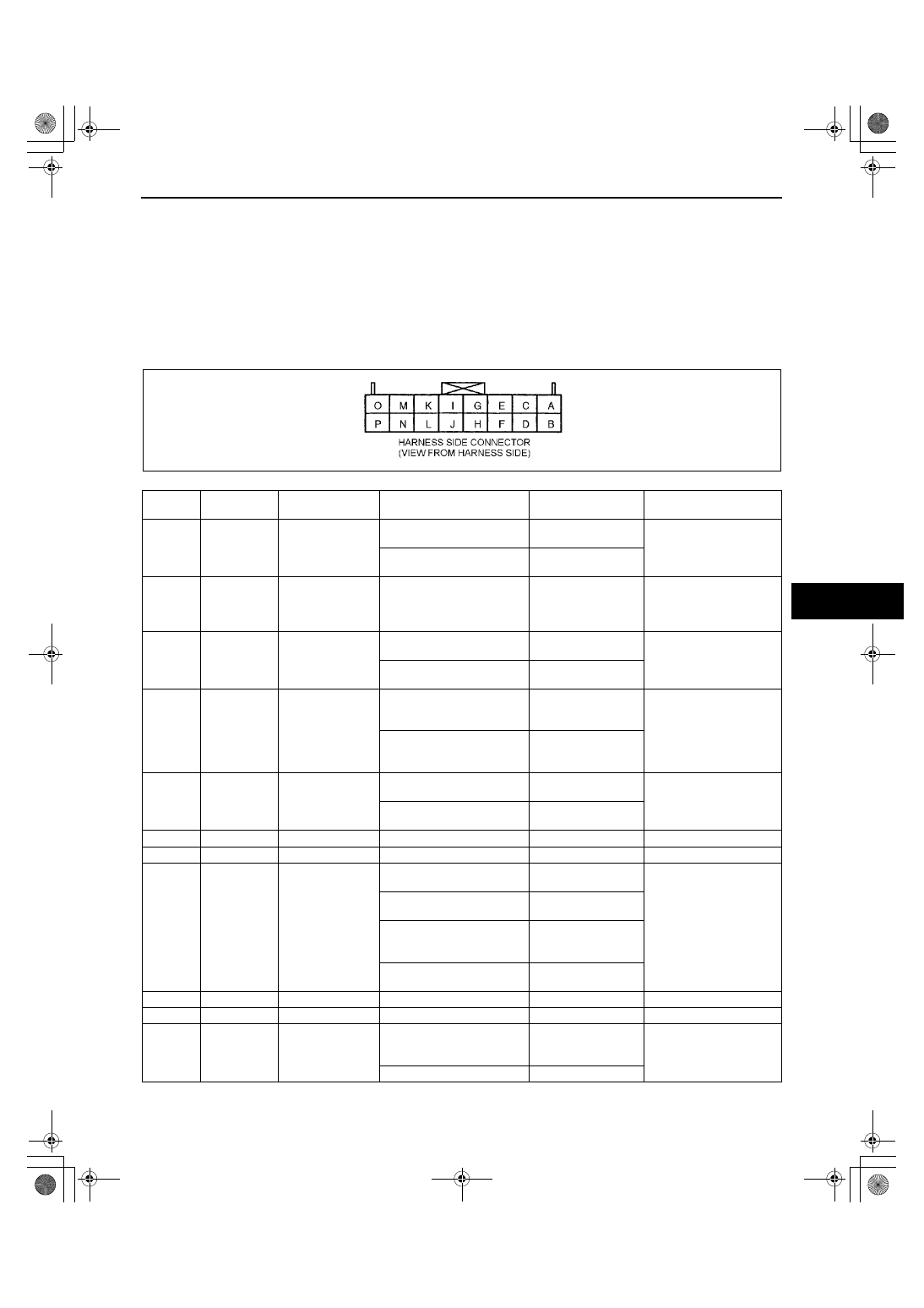
1. Pull out the keyless control module with the connector connected.
2. Measure the voltage at the keyless control module terminals (other than terminal L) as indicated below.
•
If not as specified, inspect the parts listed under “Action.”
3. Disconnect the negative battery cable.
4. Disconnect the keyless control module connector and inspect for continuity between terminal L and bracket.
5. Inspect for continuity at terminal L as indicated below.
6. If the parts and wiring harnesses are okay but the system still does not work properly, perform the
troubleshooting.
Terminal Voltage List (Reference)
Terminal
Signal
Connected to
Test condition
Voltage (V)/
Continuity
Action
A
IG1
R. WIPE 10 A fuse
Ignition switch is at ON
position
B+
•
Inspect R. WIPE 10 A
fuse
•
Inspect related
harness
Ignition switch is at LOCK or
ACC position
Below 1.0
B
Power supply ROOM 10 A fuse
Under any condition
B+
•
Inspect ROOM 10 A
fuse
•
Inspect related
harness
C
Door open/
closed
Door switch
Any door is open (any door
switch is on)
Below 1.0
•
Inspect door switches
•
Inspect related
harness
All door are closed (door
switches are off)
B+
D
Liftgate open/
closed
Cargo
compartment light
switch
Liftgate is open (cargo
compartment light switch is
on)
Below 1.0
•
Inspect cargo
compartment light
switch
•
Inspect related
harness
Liftgate is closed (cargo
compartment light switch is
off)
B+
E
Horn
Horn relay
Transmitter panic button is
pressed
Alternates between
B+ and Below 1.0
•
Inspect transmitter
•
Inspect horn relay
•
Inspect related
harness
Transmitter panic button is
not pressed
B+
F
-
-
-
-
-
G
-
-
-
-
-
H
Hazard
Flasher control
module
Transmitter panic button is
pressed
Alternates between
B+ and Below 1.0
•
Inspect flasher control
module
•
Inspect related
harness
Transmitter LOCK button is
pressed
B+
→
Below 1.0
→
B+
Transmitter UNLOCK button
is pressed once
B+
→
Below
1.0
→
B+
→
Below
1.0
→
B+
No transmitter buttons are
pressed
B+
I
-
-
-
-
-
J
-
-
-
-
-
K
Unlock output
Door lock control
module
Transmitter UNLOCK button
is pressed twice within 5
seconds. (second value)
5
→
Below 1.0
→
5
•
Inspect door lock
control module
•
Inspect related
harness
Other
5
Y3U914WA6
1712-1U-01G(09-14).fm 11 ページ 2001年6月29日 金曜日 午前10時32分