Mazda Protege 5. Manual - part 307


  Index      Mazda     Mazda Protege 5 - service repair manual 2002 year


Search            


Content   ..  305  306  307  308   ..


Mazda Protege 5. Manual - part 307


SYMPTOM TROUBLESHOOTING 

09–03–7

09–03

End Of Sie

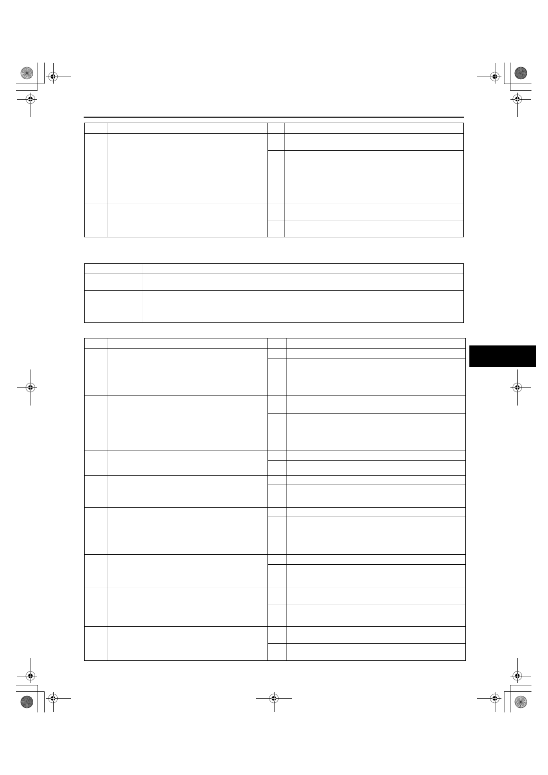
NO.3 TRANSMITTER ID CODE CANNOT BE REPROGRAMMED

A3U090369000W08

Diagnostic procedure

End Of Sie

7

INSPECT KEYLESS CONTROL MODULE OR 
WIRING HARNESS (BETWEEN KEYLESS 
CONTROL MODULE AND DOOR SWITCHES, 
CARGO COMPARTMENT LIGHT SWITCH FOR 
CONTINUITY)

Open the driver-side door.

Open the liftgate.

Is there continuity between keyless control 
module connector terminal C, D and ground?

Yes Replace keyless control module and reprogram keyless 

control module ID code, then go to next step.

No

Repair wiring harness between keyless control module 
and door switches, cargo compartment light switch then go 
to next step.

8

RECHECK MALFUNCTION SYMPTOM AFTER 
REPAIR

Does keyless entry system operate properly?

Yes Troubleshooting completed.

Explain repairs to customer.

No

Recheck malfunction symptoms, then repeat from Step 1 if 
malfunction recurs.

STEP

INSPECTION

ACTION

3

Transmitter ID code cannot be reprogrammed

DESCRIPTION

Malfunction in transmitter battery, transmitter keyless control module bracket, keyless control module 
bracket ground screw or keyless control module circuit.

POSSIBLE 

CAUSE

Malfunction in transmitter battery, transmitter, keyless control module bracket, keyless control module 
bracket ground screw or keyless control module circuit
— Transmitter battery, transmitter, keyless control module bracket, keyless control module bracket 

ground screw or keyless control module malfunction

STEP

INSPECTION

ACTION

1

INSPECT TRANSMITTER BATTERY 
INSTALLATION AND TYPE

Visually inspect transmitter battery.

Are below items okay?
— Transmitter battery installation (correct polarity)
— Battery type (CR2025)

Yes Go to next step.

No

Set transmitter battery properly or replace with specified 
transmitter battery (CR2025), then go to Step 8.

2

INSPECT TRANSMITTER BATTERY TERMINALS 
FOR RUST AND POOR CONNECTION

Visually inspect transmitter.
— Is there rust on transmitter battery terminals 

(positive or negative pole)?

— Is there poor connection between terminals 

and battery?

Yes Replace transmitter battery or repair transmitter battery 

terminal, then go to Step 8.

No

Go to next step.

3

INSPECT TRANSMITTER BATTERY

Inspect transmitter battery.

Is battery voltage normal?

Yes Go to next step.

No

Replace transmitter battery, then go to Step 8.

4

INSPECT KEYLESS CONTROL MODULE 
BRACKET INSTALLATION

Is keyless control module bracket installed 
securely?

Yes Go to next step.

No

Install bracket securely, then go back to Step 6 of keyless 
entry system preliminary inspection.

5

INSPECT GROUND SCREW INSTALLATION 
BETWEEN KEYLESS CONTROL MODULE AND 
KEYLESS CONTROL MODULE BRACKET

Are keyless control module and keyless control 
module bracket connected securely to ground 
screw?

Yes Go to next step.

No

Install screw securely, then go back to Step 6 of keyless 
entry system preliminary inspection.

6

CHECK TO SEE WHETHER MALFUNCTION IS IN 
TRANSMITTER BATTERY OR ELSEWHERE

Replace with a known good transmitter battery.

Does keyless entry system operate properly?

Yes Replace transmitter battery, then go to Step 8.

No

Go to next step.

7

CHECK TO SEE WHETHER MALFUNCTION IS IN 
TRANSMITTER OR KEYLESS CONTROL MODULE

Reprogram keyless control module ID code 
using another known good transmitter.

Does keyless entry system operate properly?

Yes Replace transmitter and reprogram transmitter ID code, 

then go to next step.

No

Replace keyless control module and reprogram keyless 
control module ID code, then go to next step.

8

RECHECK MALFUNCTION SYMPTOM AFTER 
REPAIR

Does keyless entry system operate properly?

Yes Troubleshooting completed.

Explain repairs to customer.

No

Recheck malfunction symptoms, then repeat from Step 1 if 
malfunction recurs.

1712-1U-01G(09-03).fm  7 ページ  2001年6月29日 金曜日 午前10時28分

BODY PANELS 

09–10–1

09–10

09–10

BODY PANELS

FUEL-FILLER LID ADJUSTMENT . . . . .  09–10–1
FUEL-FILLER LID 

REMOVAL/INSTALLATION . . . . . . . . .  09–10–1

HOOD ADJUSTMENT. . . . . . . . . . . . . . .  09–10–2
HOOD REMOVAL/INSTALLATION  . . . .  09–10–3
TRUNK LID ADJUSTMENT  . . . . . . . . . .  09–10–3
TRUNK LID REMOVAL/INSTALLATION 09–10–4

Balance Spring Removal Note . . . . . . .  09–10–2

FRONT BUMPER 

REMOVAL/INSTALLATION . . . . . . . . .  09–10–5

Front Bumper Removal Note . . . . . . . .  09–10–5

Front Bumper Installation Note . . . . . . . 09–10–6

FRONT BUMPER 

DISASSEMBLY/ASSEMBLY . . . . . . . . . 09–10–6

Front Bumper Mesh Removal Note. . . . 09–10–6
Hole Cover Removal Note  . . . . . . . . . . 09–10–7

REAR BUMPER 

REMOVAL/INSTALLATION . . . . . . . . . . 09–10–7

4SD . . . . . . . . . . . . . . . . . . . . . . . . . . . . 09–10–7
5HB . . . . . . . . . . . . . . . . . . . . . . . . . . . . 09–10–7

FRONT FENDER PANEL 

REMOVAL/INSTALLATION . . . . . . . . . . 09–10–8

End of Toc

FUEL-FILLER LID ADJUSTMENT

A3U091042410W01

1. Measure the gap and height between the fuel-

filler lid and the body.

If not as specified, loosen the fuel-filler lid 
installation bolts, and reposition the fuel-filler 
lid.

Clearance

a: 2.1—4.1 mm {0.09—0.16 in}
b: 2.5—4.5 mm {0.10—0.17 in}
c: 2.5—4.5 mm {0.10—0.17 in}
d: 2.3—4.3 mm {0.10—0.16 in}
e: –0.5—1.5 mm {–0.020—0.059 in}

2. Tighten the bolts.

End Of Sie

FUEL-FILLER LID REMOVAL/INSTALLATION

A3U091042410W02

1. Remove the bolts, then remove the fuel-filler lid.
2. Install in the reverse order of removal.
3. Adjust the fuel-filler lid. (See 09–10–1 FUEL-

FILLER LID ADJUSTMENT.)

End Of Sie

X3U910WA0

X3U910WA1

1712-1U-01G(09-10).fm  1 ページ  2001年6月29日 金曜日 午前10時29分

BODY PANELS 

09–10–2

HOOD ADJUSTMENT

A3U091052310W01

1. Measure the gap and height between the bonnet 

and the body.

If not as specified, adjust the gap and height.

Clearance

a: 3.7—8.3 mm {0.15—0.33 in}
b: 4.0—8.0 mm {–0.16—0.32 in}
c: 3.0—5.0 mm {0.12—0.20 in}
d:–1.0—1.0 mm {–0.04—0.04 in}

Gap Adjustment

1. Loosen the bonnet installation bolts and 

reposition the bonnet.

Tightening torque

18.6—28.4 N·m {1.9—2.9 kgf·m, 13—20 ft·lbf}

2. Tighten the bolts.

Height Adjustment

1. Turn the stop rubber to adjust the height of the 

bonnet.

End Of Sie

Y3E7710W001

Y3E7710W002

X5U910WA3

1712-1U-01G(09-10).fm  2 ページ  2001年6月29日 金曜日 午前10時29分

BODY PANELS 

09–10–3

09–10

HOOD REMOVAL/INSTALLATION

A3U091052310W02

Warning

••••

Removing the hood without supporting it can be dangerous. The hood may fall and injure you. 
Always perform these procedures together with at least another person.

1. Disconnect the windshield washer hose.
2. To remove the hood hinge, remove the front fender panel. (See 09–10–8 FRONT FENDER PANEL 

REMOVAL/INSTALLATION.)

3. Remove in the order indicated in the table.

4. Install in the reverse order of removal.
5. Adjust the hood. (See 09–10–2 HOOD 

ADJUSTMENT.)

End Of Sie

TRUNK LID ADJUSTMENT

A3U091052610W01

1. Measure the gap between the trunk lid and the 

body panel.

If not as specified, loosen the trunk lid hinge 
installation nuts and reposition the trunk lid.

Clearance

a: 3.3—5.3 mm {0.13—0.20 in}
b: –1.0—1.0 mm {–0.040—0.039 in}
c: 5.0—11.0 mm {0.20—0.43 in}

2. Tighten the nuts.

End Of Sie

1

Hood insulator (FP)

2

Shroud seal weatherstrip

3

Parting seal weatherstrip

4

Hood

5

Hood hinge

6

Hood stay

Y3U910WA0

X3U910WA6

1712-1U-01G(09-10).fm  3 ページ  2001年6月29日 金曜日 午前10時29分


Content   ..  305  306  307  308   ..