Mazda Protege 5. Manual - part 299


  Index      Mazda     Mazda Protege 5 - service repair manual 2002 year


Search            


Content   ..  297  298  299  300   ..


Mazda Protege 5. Manual - part 299


AIR BAG SYSTEM 

08–10–22

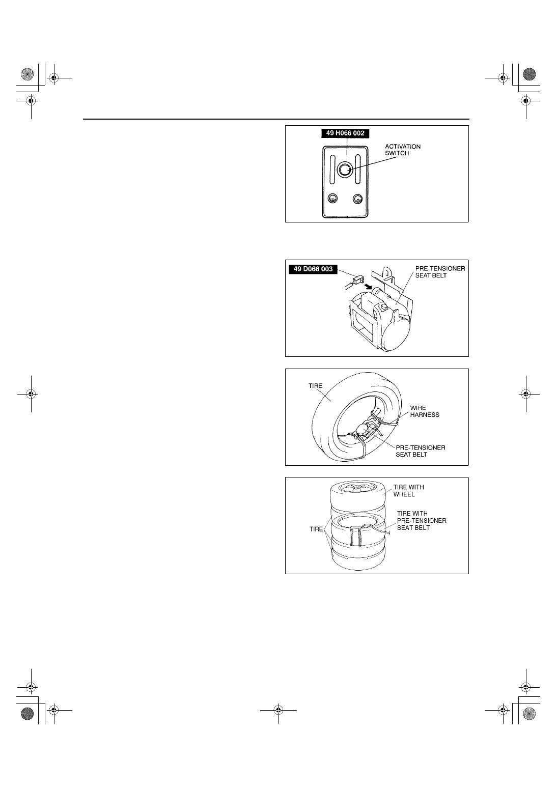
11. Press the activation switch on the SST 

(Deployment tool) to deploy the side air bag 
module.

Pre-tensioner seat belt

1. Remove the pre-tensioner seat belt.
2. Connect the SST (49 D066 003) to the pre-

tensioner seat belt as shown in the figure.

Warning

••••

If the pre-tensioner seat belt is not 
properly installed to the tire, serious 
injury may occur when the pre-tensioner 
part is deployed. When installing the pre-
tensioner seat belt to the tire, make sure 
the pre-tensioner part is inside the tire.

3. With the pre-tensioner part inside the tire, tie the 

pre-tensioner seat belt to the tire. Wrap the wire 
harness through the tire and around the pre-
tensioner seat belt at least four times.

4. Stack the tire with the pre-tensioner seat belt on 

top of two tires. Stack a tire on top of the three 
tires. Stack another tire that has a wheel on top of 
the four tires.

Y3U810WAM

Z3U0810W005

Z3U0810W006

YLE8130W201

1712-1U-01G(08-10).fm  22 ページ  2001年6月29日 金曜日 午前10時24分

AIR BAG SYSTEM 

08–10–23

08–10

5. Tie all tires together with wire.

6. Connect the SST (49 H066 002) to the SST (49 

D066 003).

7. Connect the red clip of the SST (49 H066 002) to 

the positive battery terminal and the black clip to 
the negative battery terminal.

8. Verify that the red light on the SST (49 H066 002) 

is illuminated.

9. Make sure all persons are standing at least 6 m 

{20 ft} from the vehicle.

10. Press the activation switch on the SST (49 H066 

002) to deploy the pre-tensioner seat belt.

End Of Sie

AIR BAG MODULE AND PRE-TENSIONER SEAT BELT DISPOSAL PROCEDURES

A3U081057000W03

Warning

••••

Before scrapping a vehicle with a live (undeployed) air bag module and pre-tensioner seat belt, 
deploy the air bag module. Never dispose of a live (undeployed) air bag module and pre-tensioner 
seat belt.

••••

The air bag module and pre-tensioner seat belt are very hot immediately after it is deployed. You 
can get burned. Do not touch the air bag module and pre-tensioner seat belt for at least 15 minutes 
after deployment.

••••

Pouring water on the deployed air bag module and pre-tensioner seat belt are dangerous. The 
water will mix with the residual gases to form a gas that can make breathing difficult. Do not pour 
water on the deployed air bag module and pre-tensioner seat belt.

••••

The deployed air bag module and pre-tensioner seat belt may contain deposits of sodium 
hydroxide, a caustic by product of the gas-generated combustion. If this substance gets into your 
eyes or on your hands, it can cause irritation and itching. When handling the deployed air bag 
module and pre-tensioner seat belt, wear gloves and safety glasses.

1. Put on gloves and safety glasses.
2. Put the deployed air bag module or pre-tensioner seat belt in a plastic bag, seal it, and then dispose of it.
3. Wash your hands after removing your gloves.

End Of Sie

XME8126W008

XME8126W009

XME8126W010

1712-1U-01G(08-10).fm  23 ページ  2001年6月29日 金曜日 午前10時24分

AIR BAG SYSTEM 

08–10–24

INSPECTION OF SST (DEPLOYMENT TOOL)

A3U081001078W01

Use the SST (Deployment tool) to deploy a live 
(undeployed) air bag module before disposing of 
it.

Before using the SST (Deployment tool), inspect 
its operation.

Inspection Procedure

1. Follow the steps below to verify that the SST (Deployment tool) is operating correctly.

If not as specified, do not use the SST (Deployment tool) because it may cause the air bag module to 
unexpectedly deploy upon connection to the air bag module.

End Of Sie

X3U810WB7

Step

Inspection procedure

Light condition

Green

Red

1

Connect red clip to positive 
battery terminal and black clip 
to negative battery terminal.

On

Off

2

Connect connectors A and B 
of SST (Deployment tool).

Off

On

3

Press activation switch.

On

Off

X3U810WB8

1712-1U-01G(08-10).fm  24 ページ  2001年6月29日 金曜日 午前10時24分

SEAT BELT 

08–11–1

08–11

08–11

SEAT BELT

FRONT SEAT BELT 

REMOVAL/INSTALLATION . . . . . . . . .  08–11–1

REAR SEAT BELT 

REMOVAL/INSTALLATION . . . . . . . . .  08–11–1

4SD  . . . . . . . . . . . . . . . . . . . . . . . . . . .  08–11–2
5HB  . . . . . . . . . . . . . . . . . . . . . . . . . . .  08–11–2

REAR CENTER SEAT BELT 

REMOVAL/INSTALLATION . . . . . . . . .  08–11–3

4SD  . . . . . . . . . . . . . . . . . . . . . . . . . . .  08–11–3
5HB  . . . . . . . . . . . . . . . . . . . . . . . . . . .  08–11–3

FRONT BUCKLE 

REMOVAL/INSTALLATION . . . . . . . . .  08–11–3

REAR BUCKLE 

REMOVAL/INSTALLATION . . . . . . . . . . 08–11–4

SEAT BELT INSPECTION . . . . . . . . . . . . 08–11–4

Belt  . . . . . . . . . . . . . . . . . . . . . . . . . . . . 08–11–4
ELR . . . . . . . . . . . . . . . . . . . . . . . . . . . . 08–11–4
ALR . . . . . . . . . . . . . . . . . . . . . . . . . . . . 08–11–4

BUCKLE SWITCH INSPECTION . . . . . . . 08–11–5
CHILD RESTRAINT SEAT ANCHOR 

REMOVAL/INSTALLATION . . . . . . . . . . 08–11–5

ISOFIX Anchor  . . . . . . . . . . . . . . . . . . . 08–11–5
Tether Anchor . . . . . . . . . . . . . . . . . . . . 08–11–5

End of Toc

FRONT SEAT BELT REMOVAL/INSTALLATION

A3U081157630W01

Warning

••••

Handling the front seat belt (pre-tensioner seat belt) or the side air bag sensor improperly can 
accidentally deploy the pre-tensioner or the side air bag module, which may seriously injure you. 
Read SERVICE WARNINGS before handling the front seat belt or working around the B-pillar 
areas. (See 08–10–3 AIR BAG SYSTEM SERVICE WARNINGS.)

Note

The side air bag sensor is located in the B-pillar.

Caution

••••

The ELR has a spring that will unwind if the retractor's cover is removed. The spring cannot be 
rewound by hand. If this occurs, the ELR will not work properly. Therefore, do not disassemble the 
retractor.

1. Disconnect the negative battery cable.
2. Remove the B-pillar lower trim. (See 09–17–10 B-PILLAR LOWER TRIM REMOVAL.) (See 09–17–11 B-

PILLAR LOWER TRIM INSTALLATION.)

3. Remove in the order indicated in the table.

4. Install in the reverse order of removal.

End Of Sie

1

Anchor cover

2

Front seat belt

X3U811WA0

1712-1U-01G(08-11).fm  1 ページ  2001年6月29日 金曜日 午前10時25分


Content   ..  297  298  299  300   ..