Mazda Protege 5. Manual - part 267


  Index      Mazda     Mazda Protege 5 - service repair manual 2002 year


Search            


Content   ..  265  266  267  268   ..


Mazda Protege 5. Manual - part 267


ENGINE SPEED SENSING POWER STEERING 

06–12–17

06–12

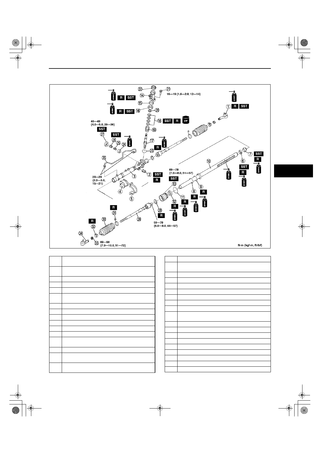
STEERING GEAR AND LINKAGE ASSEMBLY

A3U061232960W04

1. Assemble in the order indicated in the table.

.

Z3U0612W014

1

Tie-rod end boot
(See 06–12–18 Tie-rod End Boot Assembly Note)

2

Mounting rubber
(See 06–12–18 Mounting Rubber Assembly Note)

3

Gear housing

4

Mount

5

Mounting bracket

6

Oil seal
(See 06–12–19 Oil Seal Assembly Note 1)

7

Inner guide

8

O-ring

9

Seal  ring

10

Steering rack

11

O-ring

12

U-gasket

13

Holder
(See 06–12–20 Holder Assembly Note)

14

Valve housing

15

Oil seal
(See 06–12–20 Oil Seal Assembly Note 2)

16

Upper bearing
(See 06–12–21 Upper Bearing Assembly Note)

17

Pinion shaft

18

Seal ring
(See 06–12–21 Seal Ring Assembly Note)

19

Control valve

20

Snap ring

21

Socket bolt

22

Dust cover

23

O-ring

24

Support yoke

25

Yoke spring

26

Adjusting cover
(See 06–12–21 Adjusting Cover Assembly Note)

27

Locknut (Adjusting cover)

28

Washer

29

Tie-rod

30

Boot

31

Boot wire

32

Boot band

33

Locknut (Tie-rod End)

34

Tie-rod End

35

Oil pipe

1712-1U-01G(06-12).fm  17 ページ  2001年6月29日 金曜日 午前10時17分

ENGINE SPEED SENSING POWER STEERING 

06–12–18

Tie-rod End Boot Assembly Note

1. Wipe the grease off the ball joint.
2. Put a small amount of lithium-based grease into a new dust boot.
3. Install the dust boot onto the tie-rod end using the 

SST and a press.

4. Wipe away any excessive grease.

Mounting Rubber Assembly Note

1. Apply soapy water to the rubber part of the mounting rubber.
2. Press the mounting rubber until the mounting 

rubber end comes out completely from the gear 
housing using the SSTs and a press.

Note

Mounting rubber end and steel plate shall be 
aligned.

3. Reverse the gear housing, then press the 

mounting rubber until the mounting rubber end 
comes completely out the other side.

X3U612WB1

X3U612WB2

X3U612WB3

1712-1U-01G(06-12).fm  18 ページ  2001年6月29日 金曜日 午前10時17分

ENGINE SPEED SENSING POWER STEERING 

06–12–19

06–12

Oil Seal Assembly Note 1

1. Install a new O-ring and new seal ring to the rack piston.
2. After installing the seal ring, seat it properly at the piston circumference.
3. Install a new oil seal to the SST (49 B032 319) 

using the SST (49 B032 318).

4. Remove the SST (49 B032 318).

5. Using the SST, place the oil seal at the edge of 

the steering rack's piston and remove the SST.

6. Install a new inner guide to the steering rack.

Caution

••••

When pressing in, do not apply a load 
pressure of more than 39.2 MPa {400 kgf/
cm

2

, 5,690 psi}. Doing so will damage the 

oil seal and inner guide.

7. After installing the steering rack to the gear 

housing, press the oil seal and inner guide using 
the SST until the force required suddenly 
increases.

Z3U0612W005

Z3U0612W006

X3U612WB6

1712-1U-01G(06-12).fm  19 ページ  2001年6月29日 金曜日 午前10時17分

ENGINE SPEED SENSING POWER STEERING 

06–12–20

Holder Assembly Note

1. Apply grease to the U-gasket and O-ring.
2. Assemble the U-gasket and O-ring into the holder.
3. Assemble the SST to the steering rack.

4. Assemble the holder using the SST.

5. Stake the holder to the cylinder using a punch.

Oil Seal Assembly Note 2

1. Apply grease to a new oil seal.
2. Press in the new oil seal using the SSTs.

Z3U0612W007

X3U612WB8

X3U612WB9

A3U0612W014

1712-1U-01G(06-12).fm  20 ページ  2001年6月29日 金曜日 午前10時17分


Content   ..  265  266  267  268   ..