Mazda Protege 5. Manual - part 265


  Index      Mazda     Mazda Protege 5 - service repair manual 2002 year


Search            


Content   ..  263  264  265  266   ..


Mazda Protege 5. Manual - part 265


ENGINE SPEED SENSING POWER STEERING 

06–12–9

06–12

STEERING LOCK (ATX MODEL) INSPECTION

A3U061275990W01

1. Verify that the cable connector does not move 

when the key is in the LOCK position and that it 
moves freely with the key in other positions.

Replace the steering lock component as 
necessary.

End Of Sie

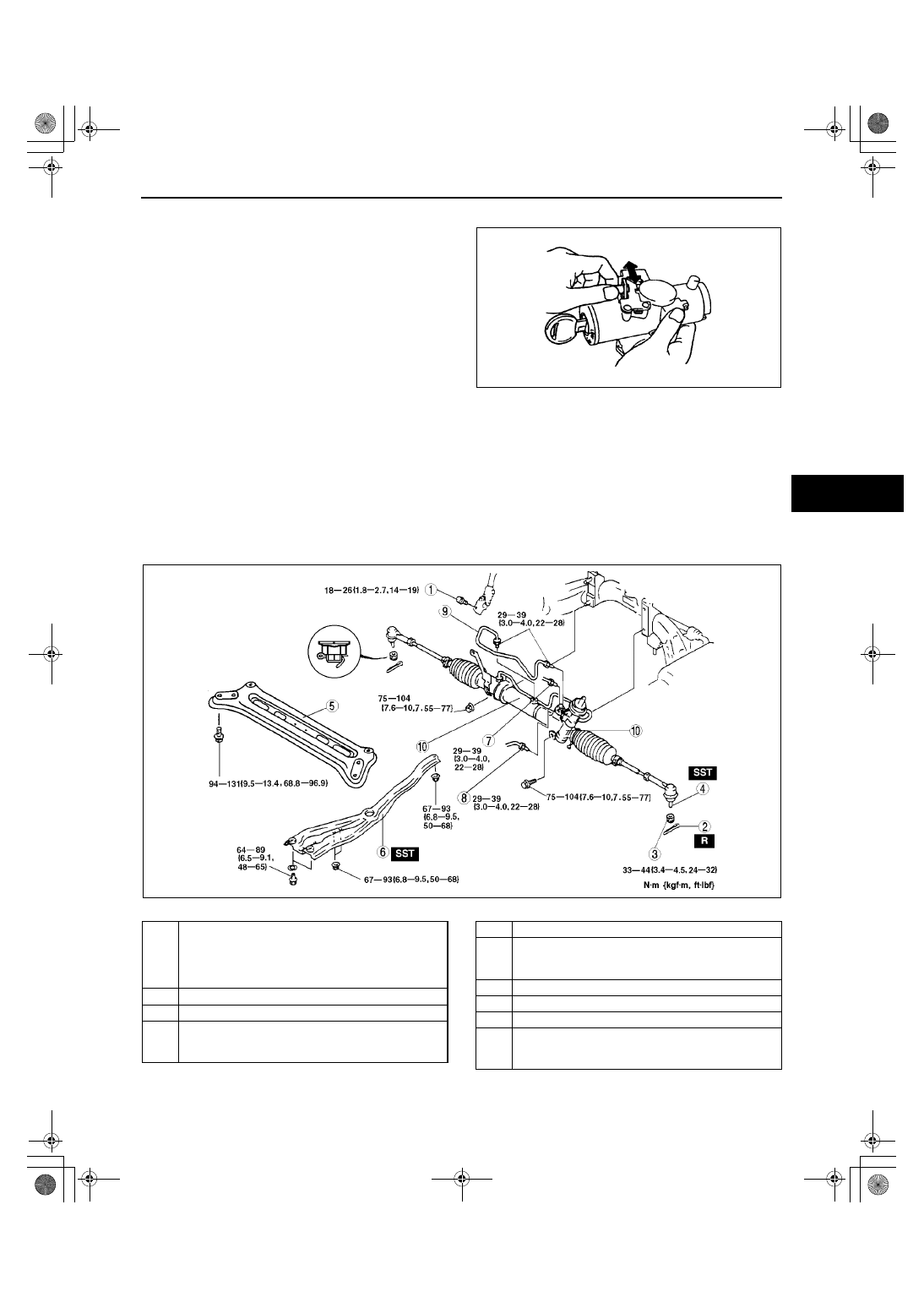
STEERING GEAR AND LINKAGE REMOVAL/INSTALLATION

A3U061232960W01

Caution

••••

Performing the following procedures without first removing the ABS wheel-speed sensor may 
possibly cause an open circuit in the harness if it is pulled by mistake. Before performing the 
following procedures, remove the ABS wheel-speed sensor (axle side) and fix it to an appropriate 
place where the sensor will not be pulled by mistake while servicing the vehicle.

1. Remove in the order indicated in the table.
2. Install in the reverse order of removal.
3. After installation, inspect the toe-in. (See 02–11–1 FRONT WHEEL ALIGNMENT.)

.

X3U612WAD

A3U0612W012

1

Bolt (intermediate shaft)
(See 06–12–10 Bolt (Intermediate Shaft) Removal 
Note)
(See 06–12–10 Bolt (Intermediate Shaft) Installation 
Note)

2

Cotter pin

3

Nut

4

Tie-rod end ball joint
(See 06–12–10 Tie-rod End Ball Joint Removal 
Note)

5

Transverse member (ZM (ATX), FS)

6

Engine mount member
(See 06–12–10 Engine Mount Member Removal 
Note)

7

Pressure pipe

8

Return pipe and clamp

9

Oil pipe

10

Steering gear and linkage
(See 06–12–10 Steering Gear and Linkage 
Removal Note)

1712-1U-01G(06-12).fm  9 ページ  2001年6月29日 金曜日 午前10時17分

ENGINE SPEED SENSING POWER STEERING 

06–12–10

Tie-rod End Ball Joint Removal Note

1. Remove the tie rod nut.
2. Separate the tie-rod end from the steering 

knuckle using the SSTs.

Engine Mount Member Removal Note

1. Set the SSTs as shown in the figure.
2. Remove the engine mount member.

Bolt (Intermediate Shaft) Removal Note

1. Mark the pinion shaft and gear housing for proper 

installation.

Steering Gear and Linkage Removal Note

1. Remove the steering gear and linkage by pulling it from the right side.

Bolt (Intermediate Shaft) Installation Note

1. Align the marks and install the intermediate shaft and bolt.

End Of Sie

X3U612WAF

Z3U0612W004

Y3U612WA8

1712-1U-01G(06-12).fm  10 ページ  2001年6月29日 金曜日 午前10時17分

ENGINE SPEED SENSING POWER STEERING 

06–12–11

06–12

STEERING GEAR AND LINKAGE DISASSEMBLY

A3U061232960W02

1. Disassemble in the order indicated in the table.

.

Z3U0612W013

1

Oil pipe

2

Tie-rod end

3

Locknut (Tie-rod end)

4

Boot band

5

Boot  wire

6

Boot

7

Tie  rod
(See 06–12–12 Tie Rod Disassembly Note)

8

Washer

9

Locknut (Adjusting cover)
(See 06–12–12 Locknut (Adjusting Cover) 
Disassembly Note)

10

Adjusting cover

11

Yoke spring

12

Support yoke

13

O-ring

14

Dust cover

15

Socket bolt

16

Pinion shaft and housing component
(See 06–12–12 Pinion Shaft and Housing 
Component Disassembly Note)

17

Pinion shaft component
(See 06–12–13 Pinion Shaft Component 
Disassembly Note)

18

Snap ring
(See 06–12–13 Snap Ring Disassembly Note)

19

Control valve component

20

Seal ring

21

Pinion shaft

22

Valve housing component

23

Upper bearing
(See 06–12–13 Upper Bearing Disassembly Note)

24

Oil seal

25

Valve housing

26

Holder
(See 06–12–13 Holder Disassembly Note)

27

U-gasket

28

O-ring

29

Steering rack

30

Seal ring

31

O-ring

32

Inner guide
(See 06–12–14 Inner Guide Disassembly Note)

33

Oil seal

34

Mounting bracket

35

Mount

36

Mounting rubber
(See 06–12–14 Mounting Rubber Disassembly 
Note)

37

Gear housing

38

Tie-rod end boot
(See 06–12–15 Tie-rod End Boot Disassembly 
Note)

1712-1U-01G(06-12).fm  11 ページ  2001年6月29日 金曜日 午前10時17分

ENGINE SPEED SENSING POWER STEERING 

06–12–12

Tie Rod Disassembly Note

1. Unclamp the washer.
2. Remove the tie-rod.

Locknut (Adjusting Cover) Disassembly Note

1. Remove the locknut using the SST.

Pinion Shaft and Housing Component Disassembly Note

1. Remove the socket bolts (2 points) which fix the 

pinion shaft and housing.

2. Hold the pinion shaft as shown, and pull the 

pinion shaft out and housing component.

X3U612WAK

A3U0612W009

X3U612WAM

X3U612WAN

1712-1U-01G(06-12).fm  12 ページ  2001年6月29日 金曜日 午前10時17分


Content   ..  263  264  265  266   ..