Mazda Protege 5. Manual - part 264


  Index      Mazda     Mazda Protege 5 - service repair manual 2002 year


Search            


Content   ..  262  263  264  265   ..


Mazda Protege 5. Manual - part 264


ENGINE SPEED SENSING POWER STEERING 

06–12–5

06–12

8. Remove the SSTs. Install and tighten the 

pressure pipe to the specified torque.

Tightening torque

30—44 N·m {3.0—4.5 kgf·m, 22—32 ft·lbf}

9. Bleed the air from the system.

End Of Sie

STEERING WHEEL AND COLUMN INSPECTION

A3U061232010W01

Steering Wheel Play Inspection

1. With the wheels in the straight-ahead position, gently turn the steering wheel to the left and right and verify that 

the play is within the specification.

If the play exceeds the specification, either the steering joints are worn or the backlash of the steering gear 
is excessive. Correct as necessary.

Play

0—30 mm {0—1.18 in}

Steering Wheel Looseness Inspection

1. Move the steering wheel as shown in the figure to 

inspect for column bearing wear, steering shaft 
joint play, steering wheel looseness, and column 
looseness.

Repair or replace as necessary.

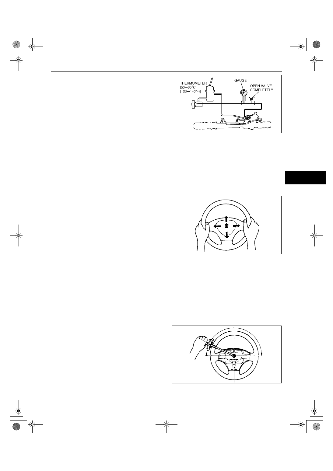
Steering Wheel Effort Inspection

1. Inspect the following points:

Tire size and tire pressure

Fluid level

Drive belt deflection

2. With the vehicle on a hard, level surface, put the wheels in the straight-ahead position.

Warning

••••

See 08-10 DRIVER-SIDE AIR BAG MODULE REMOVAL/INSTALLATION for removal/installation of 
the air bag module after inspection.

3. Remove the air bag module.
4. Start the engine and warm the power steering fluid to 50—60 

°°°°

C {123—140 

°°°°

F}.

5. Measure the steering wheel effort using a torque 

wrench.

If not within the specification, note the 
following:
— Air in system
— Fluid leakage at hose or connectors
— Function of oil pump and steering gear

Steering wheel effort

7.8 N·m {80 kgf·cm, 69 in·lbf} max.

Note

To determine whether the steering effort is 
satisfactory or not, perform the inspection on 
another vehicle of the same model and under the same conditions, and compare the results.

A3U0612W004

A3U0612W017

A3U0612W018

1712-1U-01G(06-12).fm  5 ページ  2001年6月29日 金曜日 午前10時17分

ENGINE SPEED SENSING POWER STEERING 

06–12–6

The steering wheel effort varies with conditions as shown below.
— Road conditions, such as dry or wet, and asphalt or concrete.
— Tire conditions, such as brand, wear, and tire pressure.

End Of Sie

STEERING WHEEL AND COLUMN REMOVAL/INSTALLATION

A3U061232010W02

1. Remove in the order indicated in the table.
2. Install in the reverse order of removal.

.

A3U0612W016

1

Air bag module
(See 08–10–5 DRIVER-SIDE AIR BAG MODULE 
REMOVAL/INSTALLATION)

2

Locknut

3

Steering wheel
(See 06–12–7 Steering Wheel Removal Note)
(See 06–12–8 Steering Wheel Installation Note)

4

Column cover

5

Clock spring
(See 08–10–9 CLOCK SPRING REMOVAL/
INSTALLATION)

6

Combination switch

7

Lower panel

8

Key interlock cable

9

Steering shaft
(See 06–12–8 Steering Shaft Installation Note)

10

Shaft seal

11

Set plate

12

Dust cover

13

Universal joint

14

Steering lock mounting bolts and bracket
(See 06–12–7 Steering Lock Mounting Bolts and 
Bracket Removal Note)
(See 06–12–7 Steering Lock Mounting Bolts and 
Bracket Installation Note)

15

Steering lock component

16

Cylinder outer component
(See 06–12–7 Cylinder Outer Component Removal 
Note)

1712-1U-01G(06-12).fm  6 ページ  2001年6月29日 金曜日 午前10時17分

ENGINE SPEED SENSING POWER STEERING 

06–12–7

06–12

Steering Wheel Removal Note

1. Set the vehicle in the straight-ahead position.
2. Remove the steering wheel using a suitable puller.

Caution

••••

Do not try to remove the steering wheel by hitting the shaft with a hammer. The column will 
collapse.

Steering Lock Mounting Bolts and Bracket Removal Note

1. Make a groove in the heads of the steering lock 

mounting bolts using a chisel and a hammer.

2. Remove the bolts using a screwdriver.
3. Disassemble the steering lock component.

Cylinder Outer Component Removal Note

Caution

••••

When replacing the cylinder outer component, the coil also must be replaced.

1. Set the key in the ACC position.
2. Keep pushing the button and remove the cylinder 

outer component.

Steering Lock Mounting Bolts and Bracket Installation Note

1. Assemble the steering lock component to the steering shaft.
2. Verify that the lock operates correctly.
3. Install new steering lock mounting bolts.
4. Tighten the bolts until the heads break off.

X3U612WA7

X3U612WA8

X3U612WA9

1712-1U-01G(06-12).fm  7 ページ  2001年6月29日 金曜日 午前10時17分

ENGINE SPEED SENSING POWER STEERING 

06–12–8

Steering Shaft Installation Note

Caution

••••

Do not apply a shock in the axial direction of the shaft.

1. Tighten bolt A.
2. Tighten bolt C.
3. Tighten bolt B.
4. Release the adjusting lever, and lower the 

steering shaft to the lowest position.

5. Tighten bolt D.

Steering Wheel Installation Note

1. Set the wheels in the straight-ahead position, and install the steering wheel.

End Of Sie

STEERING SHAFT INSPECTION

A3U061232100W01

1. Inspect the following.

(1) Column bearing for damage
(2) Steering shaft length

Replace the steering shaft component as 
necessary.

Length

797.4—800.4 mm {31.40—31.51 in}

2. Tilt operation

(1) Verify that the adjusting lever moves smoothly 

from unlock position to lock position.

(2) Verify that the steering shaft is fixed firmly 

when the adjusting lever is locked.

Replace the steering shaft component as 
necessary.

End Of Sie

Y3U612WA3

Y3U612WA4

X3U612WAC

1712-1U-01G(06-12).fm  8 ページ  2001年6月29日 金曜日 午前10時17分


Content   ..  262  263  264  265   ..