Mazda Protege 5. Manual - part 241


  Index      Mazda     Mazda Protege 5 - service repair manual 2002 year


Search            


Content   ..  239  240  241  242   ..


Mazda Protege 5. Manual - part 241


CLUTCH 

05–10–3

05–10

GENERAL PROCEDURES

A3U051016003W02

Clutch Pipe Removal/Installation Note

When any clutch pipe has been disconnected anytime during the procedure, add brake fluid, bleed the air, and 
inspect for leakage after the procedure has been completed.

When removing the clutch pipe, remove it using the SST (49 0259 770B). When installing the clutch pipe, 
change the clutch pipe tightening torque to allow for use of a torque wrench-SST (49 0259 770B) combination, 
and then tighten the clutch pipe using the SST (49 0259 770B). (See 00–00–15 Torque Formulas.)

End Of Sie

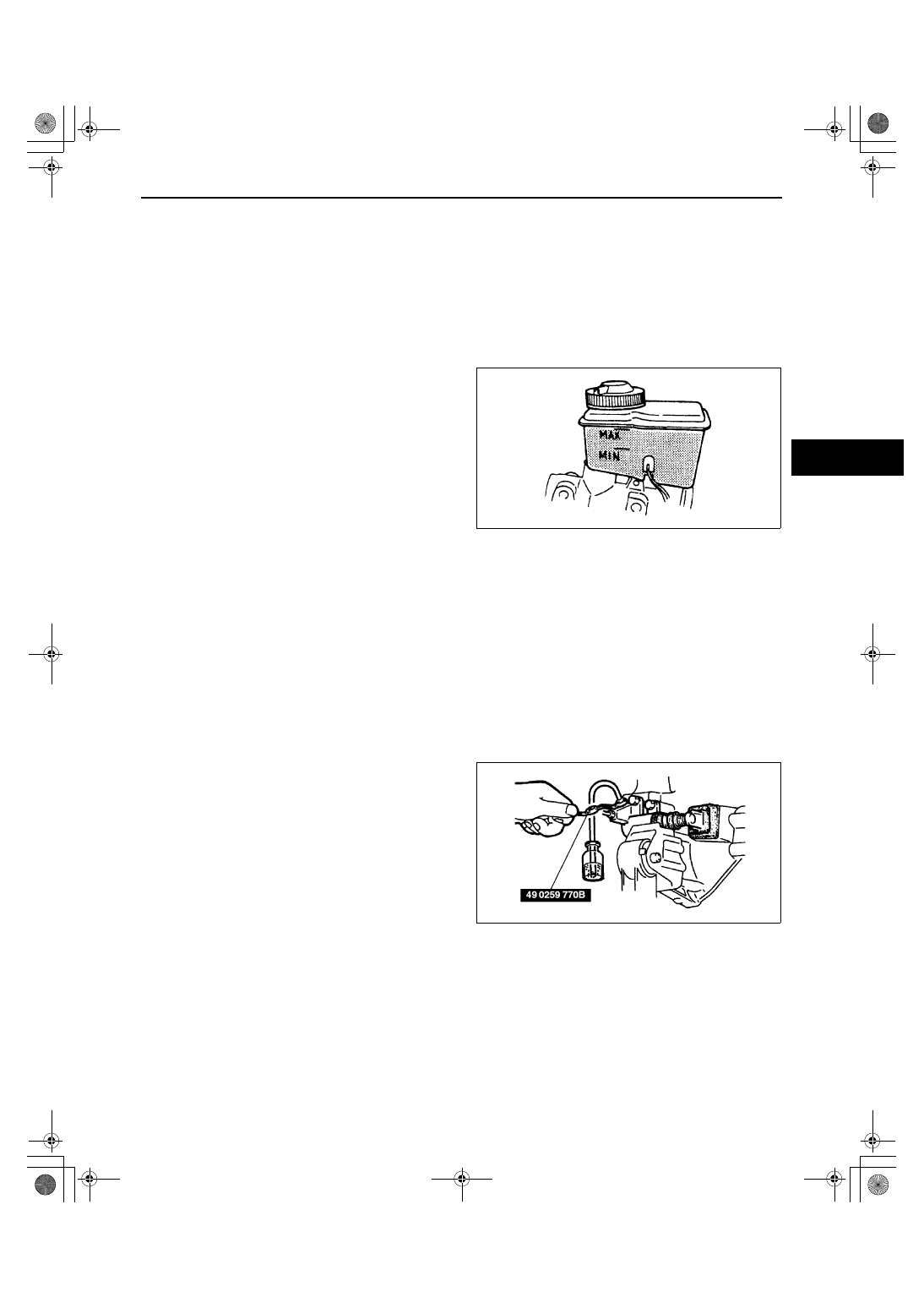
CLUTCH FLUID INSPECTION

A3U051016010W01

Note

A common reservoir is used for the clutch 
and brake system fluid.

The fluid in the reservoir must be maintained 
between the MIN/MAX level during 
replacement.

End Of Sie

CLUTCH FLUID REPLACEMENT/AIR BLEEDING

A3U051016010W02

1. Remove the splash shield.

Caution

••••

Clutch fluid will damage painted surfaces. Be sure to use a container or rags to collect it. If fluid 
does get on a painted surface, wipe it off immediately with a rag.

Note

Do not mix different brands of fluid.

Do not reuse the clutch fluid that was drained.

2. Draw the fluid from the reservoir with a suction pump.
3. Remove the bleeder cap from the clutch release cylinder and attach a vinyl hose to the bleeder plug.
4. Place the other end of the vinyl hose in a clear container.
5. Slowly pump the clutch pedal several times.
6. With the clutch pedal depressed, loosen the 

bleeder screw using the SST to let the fluid 
escape. Close the bleeder screw using the SST.

7. Repeat Steps 5 and 6 until only clean fluid is 

seen.

8. Tighten the bleeder screw.

Tightening torque

5.9—8.8 N·m {60—90 kgf·cm, 53—78 in·lbf}

9. Add fluid to the MAX mark.

10. Install the splash shield.
11. Verify the correct clutch operation.

End Of Sie

CLUTCH PEDAL INSPECTION

A3U051041030W01

Clutch Pedal Height Inspection

1. Measure the distance from the upper surface of the pedal pad to the set plate.

If not as specified, adjust the clutch pedal height.

Pedal height

210—215 mm {8.27—8.46 in} [from set plate]

U3U51001

U5U51002

1712-1U-01G(05-10).fm  3 ページ  2001年6月29日 金曜日 午前10時9分

CLUTCH 

05–10–4

Clutch Pedal Free Play Inspection

1. Depress the clutch pedal by hand until clutch 

resistance is felt, and measure the pedal free 
play.

If not as specified, adjust the clutch pedal free 
play.

Free play

0.7—3.5 mm {0.03—0.13 in}

Total free play

5.6—15.0 mm {0.23—0.59 in}

End Of Sie

CLUTCH PEDAL ADJUSTMENT

A3U051041030W02

Clutch Pedal Height Adjustment

1. Adjust the pedal height by turning locknut A and adjustment bolt B.

Pedal height

210—215 mm {8.27—8.46 in} [from set plate]

Clutch Pedal Free Play Adjustment

1. Adjust the pedal free play by turning locknut C and adjusting push rod D.

Pedal free play

0.7—3.5 mm {0.03—0.13 in}

Clutch Pedal Disengagement Stroke

1. Measure the clutch pedal disengagement stroke.

If the clutch pedal disengagement stroke is 
not within the specification, adjust the pedal 
height and pedal free play, and verify the 
pedal stroke.

Clutch pedal disengagement stroke

45—55 mm {1.8—2.1 in} (reference value)

Pedal stroke

130—140 mm {5.12—5.51 in} (reference 

value)

End Of Sie

X3U510WA0

Y3U510WA0

1712-1U-01G(05-10).fm  4 ページ  2001年6月29日 金曜日 午前10時9分

CLUTCH 

05–10–5

05–10

CLUTCH PEDAL REMOVAL/INSTALLATION

A3U051041030W03

1. Disconnect the negative battery cable.
2. Remove in the order indicated in the table.
3. Install in the reverse order of removal.
4. After installation, adjust the clutch pedal. (See 05–10–4 CLUTCH PEDAL ADJUSTMENT.)

.

End Of Sie

X3U510WA2

1

Clutch switch connector

2

Clutch switch

3

Nut

4

Clip

5

Pin

6

Bushing

7

Locknut

8

Push rod

9

Fork end

10

Nut

11

Clutch cut switch

12

Band

13

Pedal pad

14

Clutch pedal

1712-1U-01G(05-10).fm  5 ページ  2001年6月29日 金曜日 午前10時9分

CLUTCH 

05–10–6

CLUTCH MASTER CYLINDER REMOVAL/INSTALLATION

A3U051041990W01

1. Remove the battery and battery cover.

Caution

••••

Clutch fluid will damage painted surfaces. Be sure to use a container or rags to collect it. If fluid 
does get on a painted surface, wipe it off immediately with a rag.

2. Remove in the order indicated in the table.
3. Install in the reverse order of removal.

.

End Of Sie

X3U510WA3

1

Clip

2

Clutch pipe

3

Nut

4

Clutch master cylinder

5

Gasket

1712-1U-01G(05-10).fm  6 ページ  2001年6月29日 金曜日 午前10時9分


Content   ..  239  240  241  242   ..