Mazda Protege 5. Manual - part 189
REAR SUSPENSION
02–14–1
02–14
02–14
REAR SUSPENSION
REAR SUSPENSION
LOCATION INDEX . . . . . . . . . . . . . . . . 02–14–1
REAR SHOCK ABSORBER AND
SPRING REMOVAL/INSTALLATION . . 02–14–2
Coil Spring Installation Note. . . . . . . . . 02–14–3
REAR SHOCK ABSORBER
INSPECTION . . . . . . . . . . . . . . . . . . . . . 02–14–3
REAR SHOCK ABSORBER
DISPOSAL. . . . . . . . . . . . . . . . . . . . . . . 02–14–3
REAR STABILIZER
REMOVAL/INSTALLATION . . . . . . . . . 02–14–4
Stabilizer Bushing and Bracket
Installation Note . . . . . . . . . . . . . . . . . 02–14–4
STABILIZER CONTROL LINK (REAR)
INSPECTION . . . . . . . . . . . . . . . . . . . . . 02–14–4
LATERAL LINK AND TRAILING LINK
REMOVAL/INSTALLATION . . . . . . . . . . 02–14–5
Nut, Cam Plate and Adjusting Cam
Bolt Removal Note . . . . . . . . . . . . . . . 02–14–5
Front Lateral Link Removal Note . . . . . 02–14–6
Nut, Cam Plate, and Adjusting Cam
Bolt Installation Note . . . . . . . . . . . . . . 02–14–6
End of Toc
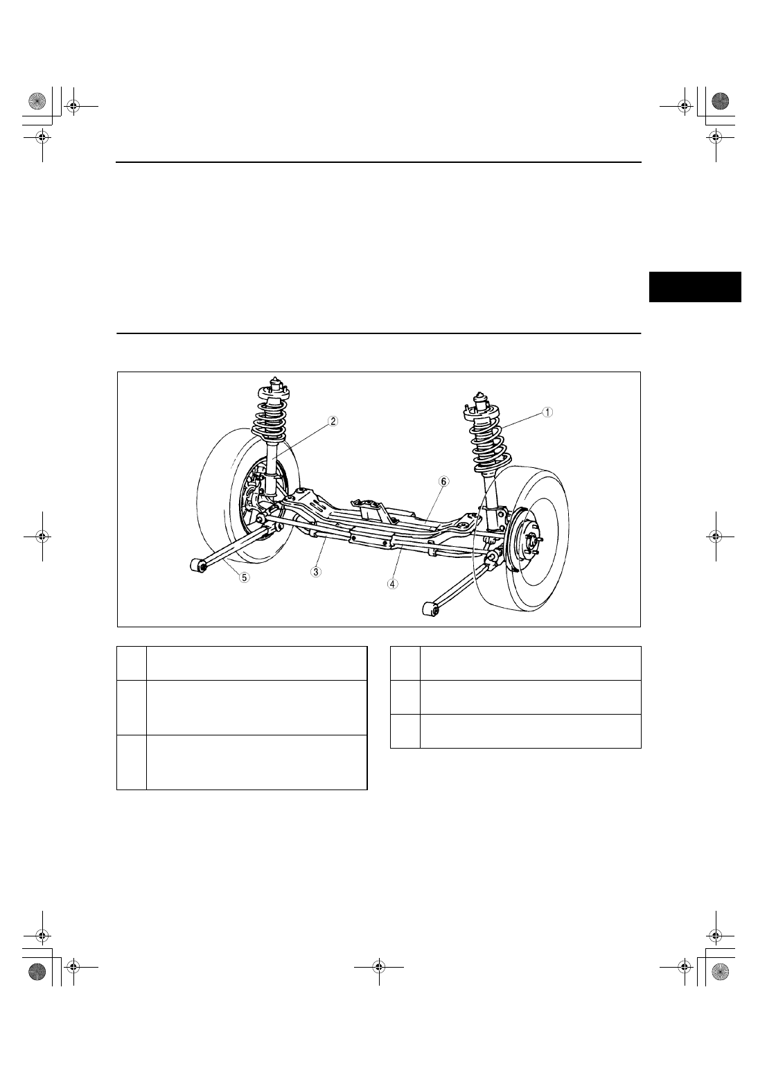
REAR SUSPENSION LOCATION INDEX
A3U021401016W01
.
End Of Sie
Z3U0214W001
1
Rear shock absorber and coil spring
(See 02–14–2 REAR SHOCK ABSORBER AND
SPRING REMOVAL/INSTALLATION)
2
Rear shock absorber
(See 02–14–3 REAR SHOCK ABSORBER
INSPECTION)
(See 02–14–3 REAR SHOCK ABSORBER
DISPOSAL)
3
Rear stabilizer and stabilizer control link
(See 02–14–4 REAR STABILIZER REMOVAL/
INSTALLATION)
(See 02–14–4 STABILIZER CONTROL LINK
(REAR) INSPECTION)
4
Lateral link
(See 02–14–5 LATERAL LINK AND TRAILING
LINK REMOVAL/INSTALLATION)
5
Trailing link
(See 02–14–5 LATERAL LINK AND TRAILING
LINK REMOVAL/INSTALLATION)
6
Rear crossmember
(See 02–14–6 REAR CROSSMEMBER REMOVAL/
INSTALLATION)
1712-1U-01G(02-14).fm 1 ページ 2001年6月29日 金曜日 午前9時55分