Mazda Protege 5. Manual - part 188


  Index      Mazda     Mazda Protege 5 - service repair manual 2002 year


Search            


Content   ..  186  187  188  189   ..


Mazda Protege 5. Manual - part 188


FRONT SUSPENSION 

02–13–7

02–13

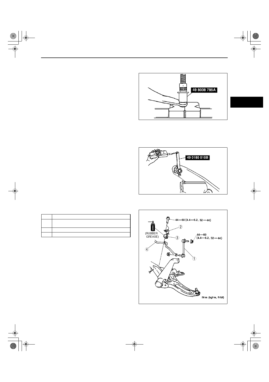
Dust Boot Installation Note

1. Wipe the grease off the ball stud.
2. Fill the inside of the new dust boot with grease.
3. Press the boot onto the ball joint using the SST.
4. Wipe away the excess grease.

End Of Sie

FRONT LOWER ARM INSPECTION

A3U021334300W02

1. Remove the lower arm from the vehicle.
2. Inspect for damage, cracks, and bending.
3. Inspect the ball joint rotation torque.

(1) Rotate the ball joint 5 times.
(2) Connect the SST to the ball stud, and 

measure the rotation torque using a pull 
scale.

Replace it if not within the specification.

Ball joint preload

1.0—4.9 N·m {10—50 kgf·cm, 9—43 in·lbf}

Pull scale reading

14—44 N {1.4—4.5 kgf, 3—10 lbf}

End Of Sie

FRONT STABILIZER REMOVAL/INSTALLATION

A3U021334100W01

1. Remove the crossmember. (See 02–13–8 FRONT CROSSMEMBER REMOVAL/INSTALLATION.)
2. Remove in the order indicated in the table.

3. Install in the reverse order of removal.
4. Inspect the front wheel alignment and adjust it if 

necessary.

Z3U0213W015

A3U0213W008

1

Stabilizer control link

2

Stabilizer bracket
(See 02–13–8 Stabilizer Bracket Installation Note)

3

Stabilizer bushing

4

Front stabilizer

Z3U0213W016

1712-1U-01G(02-13).fm  7 ページ  2001年6月30日 土曜日 午前10時2分

FRONT SUSPENSION 

02–13–8

Stabilizer Bracket Installation Note

1. Apply rubber grease to the inside surface of the stabilizer bushing.
2. Align the bushing with the inside of positioning 

plate on the stabilizer bar.

3. Install the stabilizer bracket.

End Of Sie

STABILIZER CONTROL LINK (FRONT) INSPECTION

A3U021334150W01

1. Remove the stabilizer control link from the vehicle.
2. Inspect for bending and damage.
3. Measure the ball joint starting torque.

(1) Rock the ball joint stud side to side 10 times.
(2) Rotate the ball joint stud 10 times.
(3) Measure the starting torque using a suitable 

Allen socket and a torque wrench.

Starting torque

0.2—2.5 N·m {1.4—26.0 kgf·cm, 1.3—22.0 

in·lbf}

End Of Sie

FRONT CROSSMEMBER REMOVAL/INSTALLATION

A3U021334800W01

1. For the MTX models, remove the change control rod and extension bar. (See 05–15A–4 MANUAL 

TRANSAXLE (MTX) REMOVAL/INSTALLATION [F25M-R].)

2. Remove the front exhaust pipe. (See 01–15–1 EXHAUST SYSTEM REMOVAL/INSTALLATION.) 

(See 01–15–1 EXHAUST SYSTEM REMOVAL/INSTALLATION.)

3. Remove the transverse member. (See02–13–9 TRANSVERSE MEMBER (ZM (ATX), FS) REMOVAL/

INSTALLATION)

4. Remove the steering gear and linkage. (See 06–12–9 STEERING GEAR AND LINKAGE REMOVAL/

INSTALLATION.)

5. Remove the front lower arm. (See 02–13–5 FRONT LOWER ARM REMOVAL/INSTALLATION.)

X3U213WAH

X3U213WAJ

X3U213WAK

1712-1U-01G(02-13).fm  8 ページ  2001年6月30日 土曜日 午前10時2分

FRONT SUSPENSION 

02–13–9

02–13

6. Remove in the order indicated in the table.

7. Install in the reverse order of removal.
8. Inspect the front wheel alignment as necessary.

Crossmember Component Removal Note

1. Support the crossmember using a jack and 

remove the bolts and nuts.

2. Remove the crossmember component.

End Of Sie

TRANSVERSE MEMBER (ZM (ATX), FS) REMOVAL/INSTALLATION

A3U021334890W01

1. Remove the transverse member.
2. Install the transverse member.

End Of Sie

1

Crossmember component
(See 02–13–9 Crossmember Component Removal 
Note)

2

Front stabilizer
(See 02–13–7 FRONT STABILIZER REMOVAL/
INSTALLATION)

3

Front crossmember

X3U213WAL

X3U213WAM

Y3E7414W001

1712-1U-01G(02-13).fm  9 ページ  2001年6月30日 土曜日 午前10時2分

FRONT SUSPENSION 

02–13–10

FRONT STRUT BAR REMOVAL/INSTALLATION

A3U021301015W02

1. Remove in the order indicated in the table.

2. Install in the reverse order of removal.

End Of Sie

1

Nut

2

Front strut bar

Y3A7414W002

1712-1U-01G(02-13).fm  10 ページ  2001年6月30日 土曜日 午前10時2分


Content   ..  186  187  188  189   ..