Mazda Protege 5. Manual - part 187


  Index      Mazda     Mazda Protege 5 - service repair manual 2002 year


Search            


Content   ..  185  186  187  188   ..


Mazda Protege 5. Manual - part 187


FRONT SUSPENSION 

02–13–3

02–13

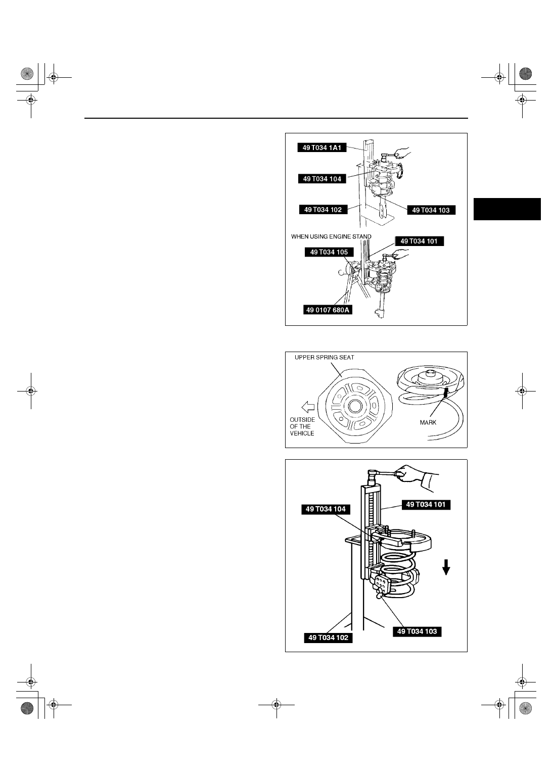
Piston Rod Nut Removal Note

1. Protect the coil spring using a piece of cloth, then 

set the SSTs.

Warning

••••

Removing the piston rod nut is 
dangerous. The shock absorber and 
spring could fly off under tremendous 
pressure and cause serious injury or 
death. Secure the shock absorber in the 
SSTs before removing the coil spring nut.

2. Compress the coil spring using the SSTs, and 

remove the piston rod nut.

Coil Spring Installation Note

1. Temporarily install the coil spring, upper spring 

seat rubber and upper spring seat on the shock 
absorber so that the lower end of the coil spring is 
seated on the step of the lower spring seat.

2. Mark the coil spring, upper spring seat rubber and 

upper spring seat for proper installation as shown 
in the figure.

3. Align the marks of the coil spring, upper spring 

seat rubber and upper spring seat. Protect the 
coil spring and upper seat spring using a piece of 
cloth, then set the SSTs.

4. Compress the coil spring using the SSTs.
5. Install the lower spring seat rubber on the lower 

spring seat.

6. Install the shock absorber so that the lower end of 

the coil spring is seated on the step of the lower 
spring seat.

7. Make sure that the marks on the shock absorber 

and upper spring seat are aligned.

8. Install the bearing, mounting rubber, and piston 

rod nut as shown in the figure, then remove the 
SSTs.

Z3U0213W003

Z3U0213W004

Z3U0213W005

1712-1U-01G(02-13).fm  3 ページ  2001年6月30日 土曜日 午前10時2分

FRONT SUSPENSION 

02–13–4

Piston rod nut tightening torque

79—109 N·m {8.0—11.2 kgf·m, 57.9—81.0 ft·lbf}

Front Shock Absorber and Spring Installation Note

1. Face the mounting block direction indicator 

toward the rear outboard position, and install the 
shock absorber.

End Of Sie

FRONT SHOCK ABSORBER INSPECTION

A3U021334700W01

1. Remove the front shock absorber from the vehicle.
2. Inspect for damage and oil leakage.
3. Inspect the rubber bushing for deterioration and wear.
4. Compress and extend the shock piston at least 3 times. Verify that the operational force does not change and 

that there is no unusual noise.
(1) Compress the shock absorber piston and release it.
(2) Verify that the piston extends fully at a normal speed.

If not as specified, replace the shock absorber.

End Of Sie

FRONT SHOCK ABSORBER DISPOSAL

A3U021334700W02

Warning

••••

Whenever drilling into a shock absorber, wear protective eye wear. The gas in the shock absorber 
is pressurized, and could spray metal chips into the eyes and face when drilling.

1. Clamp a shock absorber flat or with the piston downwards.
2. Drill a 2—3 mm {0.08—0.11 in} hole at a point 

20—30 mm {0.8—1.1 in} from the bottom of the 
tube, so that the gas can escape.

3. Turn the hole downwards.
4. The oil can be collected by moving the piston rod 

several times up and down and cutting the tube at 
the end.

5. Dispose of waste oil according to the waste 

disposal law.

Note

Shock absorber gas is nitrogen gas.

Shock absorber oil is mineral oil.

End Of Sie

X3U213WA4

Z3U0213W006

Z3U0213W007

1712-1U-01G(02-13).fm  4 ページ  2001年6月30日 土曜日 午前10時2分

FRONT SUSPENSION 

02–13–5

02–13

FRONT LOWER ARM REMOVAL/INSTALLATION

A3U021334300W01

1. Remove in the order indicated in the table.

2. Install in the reverse order of removal.

Dust Boot Removal Note

1. Remove the dust boot using a chisel, being 

careful not to damage the ball joint and the arm.

Lower Arm Bushing (Front) Removal Note

1. Cut away the projecting rubber of the lower arm bushing.
2. Set the SST onto the lower arm, and remove the 

bushing.

1

Bolt

2

Bolt (Lower arm ball joint)

3

Bracket

4

Lower arm component

5

Stopper

6

Dust boot
(See 02–13–5 Dust Boot Removal Note)
(See 02–13–7 Dust Boot Installation Note)

7

Lower arm bushing (front)
(See 02–13–5 Lower Arm Bushing (Front) Removal 
Note)
(See 02–13–6 Lower Arm Bushing (Front) 
Installation Note)

8

Lower arm bushing (rear)
(See 02–13–6 Lower Arm Bushing (Rear) Removal 
Note)
(See 02–13–6 Lower Arm Bushing (Rear) 
Installation Note)

Z3U0213W008

Z3U0213W009

A3U0213W003

1712-1U-01G(02-13).fm  5 ページ  2001年6月30日 土曜日 午前10時2分

FRONT SUSPENSION 

02–13–6

Lower Arm Bushing (Rear) Removal Note

1. Remove the lower arm bushing using the SSTs 

and a press.

Lower Arm Bushing (Rear) Installation Note

1. Align the mark of the lower arm and the small 

projection of the lower arm bushing (rear) as 
shown in the figure.

2. Set the lower arm onto the SST (49 B034 211).

3. Press the new lower arm bushing using the SST 

(49 B034 212).

Lower Arm Bushing (Front) Installation Note

1. Install the new bushing, and pull it into the lower 

arm using the SST.

A3U0213W004

A3U0213W005

A3U0213W006

A3U0213W007

1712-1U-01G(02-13).fm  6 ページ  2001年6月30日 土曜日 午前10時2分


Content   ..  185  186  187  188   ..