Mazda Protege 5. Manual - part 158


  Index      Mazda     Mazda Protege 5 - service repair manual 2002 year


Search            


Content   ..  156  157  158  159   ..


Mazda Protege 5. Manual - part 158


CHARGING SYSTEM 

01–17–2

Load test chart

Battery positive voltage with load

Back-up Current

1. Verify that the ignition switch is off and that the ignition key has been removed.
2. Disconnect the negative battery cable.

Caution

••••

Operating electrical loads while measuring the back-up current can damage the circuit tester.

3. Measure the back-up current between the negative battery terminal and the negative battery cable.

(1) If the current exceeds the maximum, remove the fuse in the main fuse block and the fuse block one by one 

while measuring the back-up current.

(2) Inspect and repair harnesses and connectors of the fuse at which the current reduces.

Back-up current

20 mA max.

End Of Sie

BATTERY RECHARGING

Warning

••••

Hydrogen gas is produced during normal battery operation. A battery-related explosion can cause 

serious injury. Keep all flames (including cigarettes), heat, and sparks away from the top and 

surrounding area of open battery cells.

Caution

••••

When disconnecting the battery, remove the negative cable first and install it last to prevent 
damage to electrical components or the battery.

••••

To prevent damage to electrical components or the battery, turn all accessories off and stop the 
engine before performing maintenance or recharging the battery.

••••

Do not quick charge for over 30 minutes. It will damage the battery.

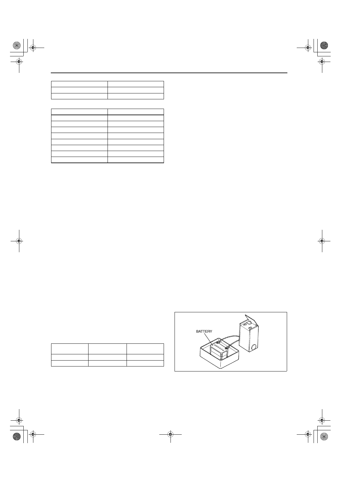
1. Place a battery in a pan of water to prevent it from 

overheating. The water level should come up 
about halfway on the battery. Keep water off the 
top of the battery.

2. Connect a battery charger to the battery.
3. Adjust the charging current as follows.

4. After the battery has been recharged, measure 

the battery positive voltage and verify that the 
battery keeps specified voltage for more than 1 hour.

If not as specified, replace the battery.

Specification

Above 12.4 V

End Of Sie

Battery

Load (A)

50D20L

150

75D23L

195

Approximate battery temp.

Minimum voltage (V)

21 

°

C {70 

°

F}

9.6

15 

°

C {60 

°

F}

9.5

10 

°

C {50 

°

F}

9.4

°

C {40 

°

F}

9.3

–1 

°

C {30 

°

F}

9.1

–7 

°

C {20 

°

F}

8.9

–12 

°

C {10 

°

F}

8.7

–18 

°

C {0 

°

F}

8.5

Battery type 

(5-hour rate)

Slow charge (A)

Quick charge 

(A)/(30 min.)

50D20L (40)

4.0—5.0

25

75D23L (52)

5.5—6.5

35

X3U117WA1

1712-1U-01G(01-17).fm  2 ページ  2001年6月29日 金曜日 午前9時47分

CHARGING SYSTEM 

01–17–3

01–17

GENERATOR REMOVAL/INSTALLATION

A3U011718300W01

Warning

••••

When the battery cables are connected, touching the vehicle body with generator terminal B will 
generate sparks. This can cause personal injury, fire, and damage to the electrical components. 
Always disconnect the battery before performing the following operation.

1. Disconnect the negative battery cable.
2. Remove in the order indicated in the table.
3. Install in the reverse order of removal.

Drive Belt Installation Note

Install the drive belt and adjust the drive belt deflection or tension. (See 01–10A–4 DRIVE BELT 
ADJUSTMENT [ZM].) (See 01–10B–4 DRIVE BELT ADJUSTMENT [FS].)

End Of Sie

GENERATOR INSPECTION

A3U011718300W02

Generator Warning Light

1. Verify that the battery is fully charged.

Charge if necessary.

2. Verify that the drive belt deflection/tension is within the specification. (See 01–10A–3 DRIVE BELT 

INSPECTION [ZM].) (See 01–10B–3 DRIVE BELT INSPECTION [FS].)

Adjust if necessary.

3. Turn the ignition switch to ON and verify that the generator warning light comes on.

If not, inspect generator warning light, wiring harnesses between the battery, generator warning light, and 
PCM terminal 42. When the generator warning light and the wiring harnesses are okay, replace the PCM.

4. Verify that the generator warning light goes out after the engine is started.

If not, inspect if any of the following DTCs are displayed: P0112, P0113, P1631, P1632, P1633, P1634. 
(See 01–02A–8 ON-BOARD DIAGNOSTIC TEST [ZM].) (See 01–02B–7 ON-BOARD DIAGNOSTIC TEST 
[FS].)

Z3U0117W001

1

Terminal B wire

2

Connector

3

Drive belt (generator)
(See 01–17–3 Drive Belt Installation Note)

4

Generator

1712-1U-01G(01-17).fm  3 ページ  2001年6月29日 金曜日 午前9時47分

CHARGING SYSTEM 

01–17–4

Generator
Voltage

1. Verify that the battery is fully charged.

Charge if necessary.

2. Verify that the drive belt deflection/tension is within the specification. (See 01–10A–3 DRIVE BELT 

INSPECTION [ZM].) (See 01–10B–3 DRIVE BELT INSPECTION [FS].)

Adjust if necessary.

3. Turn off all electrical loads.
4. Turn the ignition switch to start the engine and verify that the generator turns smoothly without any noise while 

the engine is running.

5. Measure the voltage at the terminals indicated in 

the table.

If not as specified, repair or replace the 
generator as necessary.

Standard voltage

*

: Turn the following electrical loads on and verify 

that the voltage reading increases.

Headlights

Blower motor

Rear window defroster

Current

1. Verify that the battery is fully charged.

Charge if necessary.

2. Verify that the drive belt deflection/tension is within the specification. (See 01–10A–3 DRIVE BELT 

INSPECTION [ZM].) (See 01–10B–3 DRIVE BELT INSPECTION [FS].)

Adjust if necessary.

3. Disconnect the negative battery cable.
4. Connect ammeter, capable of reading 120 A or above, between generator terminal B and the wiring harness.
5. Connect the negative battery cable.
6. Turn off all electrical loads.
7. Start the engine and increase the engine speed to 2,000—2,500 rpm.
8. Turn the following electrical loads on and verify that the current reading increases.

(1) Headlights
(2) Blower motor
(3) Rear window defroster

If generator terminal B current will not increase, repair or replace the generator as necessary.

Note

Current required for generating power varies with electrical loads applied.

Standard current (Reference)

Measuring conditions

Room temperature: 20 

°°°°

C {68 

°°°°

F}

Voltage: 13.5 V
Engine hot

*

: Must not be 0 A.

End Of Sie

Terminal

Ignition switch ON(V) Idle (V)[20 

°°°°

C {68 

°°°°

F}]

ZM

FS

ZM

FS

B

B+

13—15

P

Approx. 1

Approx.3—8

D

Approx.0

*

Y3U117WA2

Engine speed 

(rpm)

Terminal B current (A)

ZM

FS

1,000

0—60*

0—59*

2,000

0—68*

0—77*

1712-1U-01G(01-17).fm  4 ページ  2001年6月29日 金曜日 午前9時47分

IGNITION SYSTEM 

01–18–1

01–18

01–18

IGNITION SYSTEM

IGNITION COIL REMOVAL/

INSTALLATION. . . . . . . . . . . . . . . . . . .  01–18–1

IGNITION COIL INSPECTION. . . . . . . . .  01–18–2

Igniter . . . . . . . . . . . . . . . . . . . . . . . . . .  01–18–2
Ignition Coil Operation Inspection  . . . .  01–18–2

Secondary Coil Winding . . . . . . . . . . . . 01–18–2
Insulation Resistance of Case. . . . . . . . 01–18–2

HIGH-TENSION LEAD REMOVAL/

INSTALLATION  . . . . . . . . . . . . . . . . . . . 01–18–3

HIGH-TENSION LEAD INSPECTION  . . . 01–18–3

End of Toc

IGNITION COIL REMOVAL/INSTALLATION

A3U011818100W01

Caution

••••

Disconnecting the ignition coil and plug cap can tear the plug cap off and cause damage to the 
connecting part. Disconnect the ignition coil and plug cap only when each component needs to be 
replaced, and be careful not to tear and damage them.

1. Disconnect the negative battery cable.
2. Remove in the order indicated in the table.
3. Install in the reverse order of removal.

.

End Of Sie

Z3U0118W001

1

Connector

2

High-tension lead
(See 01–18–3 HIGH-TENSION LEAD REMOVAL/
INSTALLATION)

3

Ignition coil

4

Plug cap

5

Spring

1712-1U-01G(01-18).fm  1 ページ  2001年6月29日 金曜日 午前9時47分


Content   ..  156  157  158  159   ..