Mazda Protege 5. Manual - part 155


  Index      Mazda     Mazda Protege 5 - service repair manual 2002 year


Search            


Content   ..  153  154  155  156   ..


Mazda Protege 5. Manual - part 155


EMISSION SYSTEM 

01–16–10

CANISTER DRAIN CUT VALVE (CDCV) INSPECTION

A3U011618743W02

Simulation Test

1. Carry out the “Evaporative Emission Control System Inspection”. (See 01–03A–56 Evaporative System Leak 

Inspection Using Vacuum Pump.) (See 01–03B–55 Evaporative System Leak Inspection Using Vacuum 
Pump.)

If not as specified, perform the following inspection for the CDCV.

Airflow Inspection

Note

Perform the following test only when directed.

1. Disconnect the negative battery cable.
2. Remove the CDCV. (See 01–16–9 CANISTER 

DRAIN CUT VALVE (CDCV) REMOVAL/
INSTALLATION.)

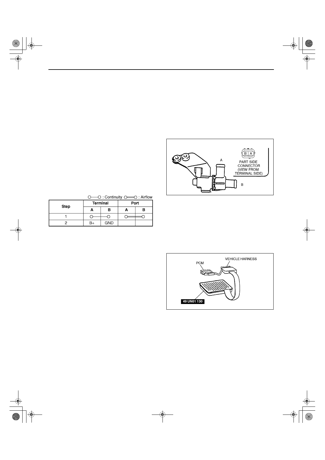
3. Inspect airflow between the ports under the 

following conditions.

If not as specified, replace the CDCV.

If as specified but the “Simulation Test” is 
failed, inspect evaporative hoses for improper 
routing, kinks or leakage, and carry out the 
“Circuit Open/Short Inspection” and repair or 
replace the parts if necessary.

Circuit Open/Short Inspection

1. Remove the PCM.
2. Connect the SST (104 Pin Breakout Box) to the 

PCM as shown.

3. Tighten the connector attaching screw.

Tightening torque

7.9—10.7 N·m {80—110 kgf·cm, 69.5—95.4 

in·lbf}

Y3U116WA1

X3U116WCA

Y3U116WAG

1712-1U-01G(01-16).fm  10 ページ  2001年6月29日 金曜日 午前9時45分

EMISSION SYSTEM 

01–16–11

01–16

4. Inspect for an open or short circuit in the following 

wiring harnesses by probing the applicable 
sensor and SST (104 Pin Breakout Box) terminals 
with ohmmeter leads.
Open circuit

GND circuit (CDCV connector terminal B and 
PCM connector terminal 18 through common 
connector)

Power circuit (CDCV connector terminal A 
and main relay connector terminal D)

Short circuit

GND circuit (CDCV connector terminal B and 
PCM connector terminal 18 through common 
connector to GND)

Power circuit (CDCV connector terminal A 
and main relay connector terminal D to GND)

5. Install the CDCV.
6. Connect the negative battery cable.

End Of Sie

CATCH TANK INSPECTION

A3U011613978W01

1. Remove the catch tank.
2. Plug the purge solenoid valve side port of the catch tank.
3. Blow from the charcoal canister side port and verify that there is no air leakage from the case.

If not as specified, replace the catch tank.

End Of Sie

PURGE SOLENOID VALVE REMOVAL/INSTALLATION

A3U011618740W01

1. Disconnect the negative battery cable.
2. Remove in the order indicated in the table.

3. Install in the reverse order of removal.

Vacuum Hose Installation Note

1. Install the vacuum hose until it contacts the stopper.

Evaporative Hose Installation Note

1. Attach the evaporative hose until it contacts the stopper.

End Of Sie

Z3U0116W997

X3U116WB0

1

Evaporative hose
(See 01–16–11 Evaporative Hose Installation Note)

2

Vacuum hose
(See 01–16–11 Vacuum Hose Installation Note)

3

Purge solenoid valve

Z3U0116W993

1712-1U-01G(01-16).fm  11 ページ  2001年6月29日 金曜日 午前9時45分

EMISSION SYSTEM 

01–16–12

PURGE SOLENOID VALVE INSPECTION

A3U011618740W02

Airflow Inspection

Note

Perform the following test only when directed.

1. Remove the purge solenoid valve. (See 01–16–11 

PURGE SOLENOID VALVE REMOVAL/
INSTALLATION.)

2. Inspect airflow between the ports under the 

following conditions.

If not as specified, replace the purge solenoid 
valve.

If as specified, inspect the vacuum hoses for 
improper routing, kinks or leakage, and carry 
out the “Circuit Open/Short Inspection” and 
repair or replace the parts if necessary.

Circuit Open/Short Inspection

1. Remove the PCM.
2. Connect the SST (104 Pin Breakout Box) to the 

PCM as shown.

3. Tighten the connector attaching screw.

Tightening torque

7.9—10.7 N·m {80—110 kgf·cm, 69.5—95.4 

in·lbf}

4. Inspect for an open or short circuit in the following 

wiring harnesses by probing the applicable 
sensor and SST (104 Pin Breakout Box) terminals 
with ohmmeter leads.
Open circuit

Power circuit (purge solenoid valve connector 
terminal A and main relay connector terminal 
D through common connector)

Control circuit (purge solenoid valve 
connector terminal B and PCM connector 
terminal 67 through common connector)

Z3U0116W992

X3U116WC1

Y3U116WAJ

X3U116WC0

1712-1U-01G(01-16).fm  12 ページ  2001年6月29日 金曜日 午前9時45分

EMISSION SYSTEM 

01–16–13

01–16

Short circuit

Power circuit (purge solenoid valve connector terminal A and main relay connector terminal D through 
common connector to GND)

Control circuit (purge solenoid valve connector terminal B and PCM connector terminal 67 through 
common connector to GND)

5. Install the purge solenoid valve.
6. Connect the negative battery cable.

End Of Sie

FUEL-FILLER CAP INSPECTION

A3U011642250W01

leakage inspection

1. Perform the following SST (Evaporative Emission System Tester MZ254AT3641) self-test.

Note

If the tester does not work correctly during self-test, see the tester operators manual for more detailed 
procedures.

(1) Verify the gas cylinder valve is closed and the control valve located on the tester is in the TEST position. All 

tester display should be off at this time.

(2) Connect the long hose (part of SST) to the tester.
(3) Connect the manifold assembly (part of SST

to the long hose as shown.

(4) Open the gas cylinder valve and verify the 

gas cylinder regulator left gauge reads 10 to 
12 psi
 (preset at factory).

If not, see the tester operators manual to 
contact tester manufacturer.

(5) Press the ON/OFF switch to turn on the SST 

and make sure the left display reads 0.0.

(6) Turn the control valve on the tester to the 

FILL position.

(7) Verify the left display reading is within 13.9 to 

14.0 inches of water.

If not, adjust the pressure using the 
regulator knob located on the right side of the tester.

(8) Turn the control valve to TEST position and press the START switch.
(9) After the 2-minute countdown (left display) is completed, the right display shows the total pressure loss for 

that period. A 0.5 inch of water loss is acceptable on the self-test.

If the loss is more than 0.5 inch of water, perform one or more self-test. If the failed test repeats, check 
for leak using the ultrasonic leak detector (part of SST).

2. Press the RESET switch to set the left display reading to 0.0.
3. Connect the fuel cap receiver assembly (part of SST) to the manifold assembly and fuel-filler cap from the 

vehicle.

If the fuel-filler cap is not a genuine part, replace it.

4. Turn the control valve to the FILL position.
5. Wait (maximum 20 s) until the left display reads 

13.9 to 14 inches of water.

If the reading is slightly below, adjust it using 
the regulator knob.

If the reading is far below, the fuel-filler cap 
has leak. Replace it.

6. Turn the control valve to the TEST position and 

press the START switch.

7. After the 2-minute countdown (left display) is 

completed, check the test result (the failed/
passed light on the tester).

If the green light turns on, the fuel-filler cap is 
OK.

If the red light turns on, the fuel-filler cap has leakage. Replace it.

8. Close the gas cylinder valve.
9. Turn the control valve to the FILL position.

10. Press the ON/OFF switch to turn off the tester.

End Of Sie

YMU116WZ1

YMU116WZ2

1712-1U-01G(01-16).fm  13 ページ  2001年6月29日 金曜日 午前9時45分


Content   ..  153  154  155  156   ..