Mazda Protege 5. Manual - part 135


  Index      Mazda     Mazda Protege 5 - service repair manual 2002 year


Search            


Content   ..  133  134  135  136   ..


Mazda Protege 5. Manual - part 135


COOLING SYSTEM 

01–12–4

ENGINE COOLANT LEAKAGE INSPECTION

A3U011215001W04

1. Inspect the coolant level.
2. Remove the radiator cap.
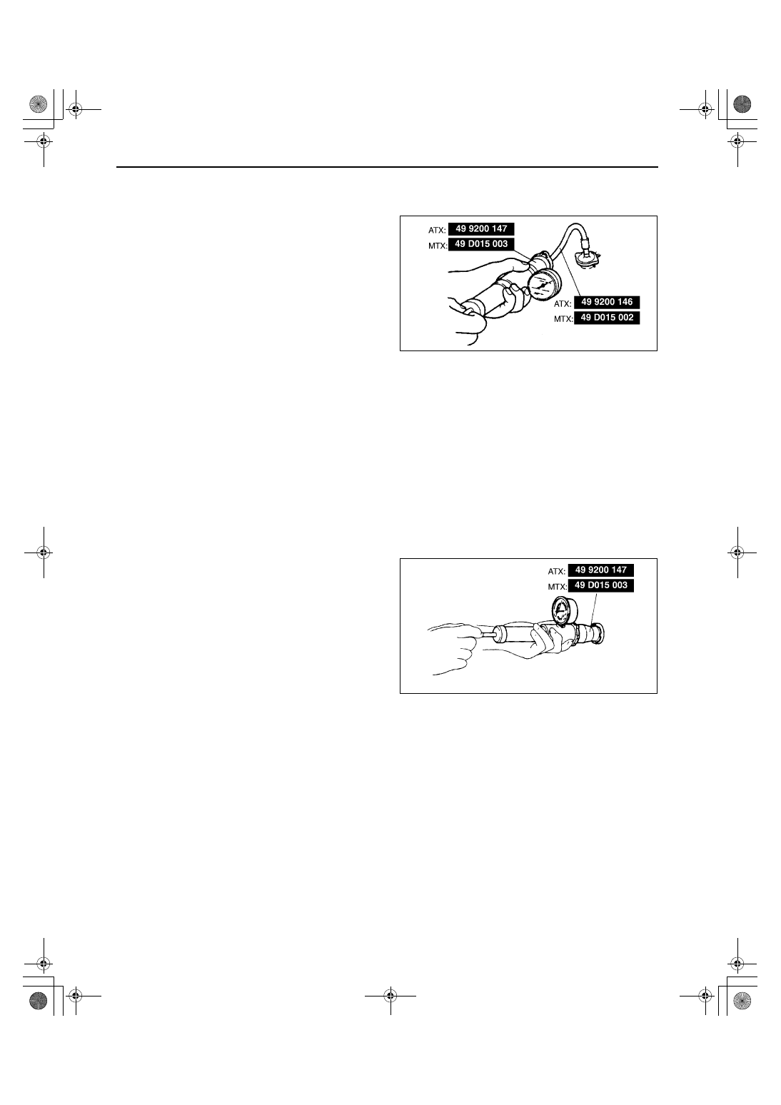
3. Connect a radiator cap tester and the SST to the 

radiator filler neck.

Caution

••••

Applying more than 123 kPa {1.25 kgf/
cm

2

, 17.8 psi} can damage the hoses, 

fittings, and other components, and 
cause leaks.

4. Apply pressure to the radiator.

Pressure

123 kPa {1.25 kgf/cm

2

, 17.8 psi}

5. Verify that the pressure is held.

If not, inspect the system for coolant leakage.

End Of Sie

RADIATOR CAP INSPECTION

A3U011215201W01

Warning

••••

Never remove the radiator cap while the engine is running, or when the engine and radiator are 
hot. Scalding coolant and steam may shoot out and cause serious injury. It may also damage the 
engine and cooling system.

••••

Turn off the engine and wait until it is cool. Even then, be very careful when removing the cap. 
Wrap a thick cloth around it and slowly turn it counterclockwise to the first stop. Step back while 
the pressure escapes.

••••

When you're sure all the pressure is gone, press down on the cap while still using the cloth, turn 
it, and remove it.

1. Attach the radiator cap to a radiator cap tester 

with the SST. Apply pressure gradually.

2. Verify that the pressure becomes stable within the 

specification.

If the pressure is held for 10 s, the radiator 
cap is normal.

Pressure

94—122 kPa {0.95—1.25 kgf/cm

2

, 13.5—17.7 

psi}

End Of Sie

RADIATOR REMOVAL/INSTALLATION

A3U011215200W01

1. Disconnect the negative battery cable.
2. Drain the engine coolant. (See 01–12–2 COOLING SYSTEM SERVICE WARNINGS.) (See 01–12–3 ENGINE 

COOLANT REPLACEMENT.)

3. Remove the fresh air duct.
4. Remove in the order indicated in the table.
5. Install in the reverse order of removal.

X3U112WA3

X3U112WA4

1712-1U-01G(01-12).fm  4 ページ  2001年6月29日 金曜日 午前9時41分

COOLING SYSTEM 

01–12–5

01–12

.

End Of Sie

THERMOSTAT REMOVAL/INSTALLATION

A3U011215171W01

1. Disconnect the negative battery cable.
2. Remove the fresh air duct.
3. Remove the air cleaner. (ZM model)
4. Drain the engine coolant. (See 01–12–2 COOLING SYSTEM SERVICE WARNINGS.) (See 01–12–3 ENGINE 

COOLANT REPLACEMENT.)

5. Remove in the order indicated in the table.

X3U112WA5

1

Upper radiator hose

2

Cooling fan motor connector, condenser fan motor 
connector

3

Lower radiator hose

4

Condenser fan

5

Cooling fan

6

Oil hose (ATX)
(See 05–17–41 OIL COOLER REMOVAL/
INSTALLATION)

7

Radiator

1

Thermostat cover

2

Thermostat cover gasket
(See 01–12–7 Thermostat Cover Gasket Installation 
Note)

3

Thermostat
(See 01–12–6 Thermostat Installation Note)

Y3U112WA1

1712-1U-01G(01-12).fm  5 ページ  2001年6月29日 金曜日 午前9時41分

COOLING SYSTEM 

01–12–6

6. Install in the reverse order of removal.

Thermostat Installation Note
ZM

1. Install the thermostat into the cylinder head with 

the jiggle pin at the top.

FS

1. Install the thermostat into the thermostat case 

with the jiggle pin and projection at the top.

2. Install the thermostat into the thermostat case, 

aligning the projection on the gasket to the 
thermostat case.

1

Lower radiator hose

2

Thermostat cover

3

Thermostat
(See 01–12–6 Thermostat Installation Note)

Z3U0112W999

X3U112WA8

X3U112WA9

1712-1U-01G(01-12).fm  6 ページ  2001年6月29日 金曜日 午前9時41分

COOLING SYSTEM 

01–12–7

01–12

Thermostat Cover Gasket Installation Note
ZM

1. Install a new gasket with the seal ring side facing 

the cylinder head.

End Of Sie

THERMOSTAT INSPECTION

A3U011215171W02

1. If the gasket of the thermostat is damaged, 

replace the thermostat assembly. (FS model)

2. Visually check that the thermostat valve is closed.
3. Place the thermostat and a thermometer in water.

Warning

••••

During inspection, the thermostat and 
water are extremely hot and they can 
cause severe burns. Do not touch the 
thermostat and water directly.

4. Heat the water and check the following.

If not as specified, replace the thermostat.

End Of Sie

X3U112WAA

Item

Engine

ZM

FS

Initial-opening temperature 

83.5—88.0 

{183—190}

80—84 

{176—183}

(

°

C {

°

F})

Full-open temperature 

100 {212}

95 {203}

(

°

C {

°

F})

Full-open lift 

(mm {in})

8.5 {0.33} min.

X3U112WAK

Z3U0112W998

1712-1U-01G(01-12).fm  7 ページ  2001年6月29日 金曜日 午前9時41分


Content   ..  133  134  135  136   ..