Mazda Protege 5. Manual - part 118


  Index      Mazda     Mazda Protege 5 - service repair manual 2002 year


Search            


Content   ..  116  117  118  119   ..


Mazda Protege 5. Manual - part 118


MECHANICAL [ZM]

01–10A–6

If the valve clearance exceeds the 
standard, replace the adjustment shim. 
(See 01–10A–6 VALVE CLEARANCE 
ADJUSTMENT [ZM].)

Standard [Engine cold]

IN: 0.25—0.31 mm {0.010—0.012 in} 

(0.28

±±±±

0.03 mm {0.011

±±±±

0.001 in})

EX: 0.25—0.31 mm {0.010—0.012 in} 

(0.28

±±±±

0.03 mm {0.011

±±±±

0.001 in})

(3) Turn the crankshaft 360

°°°°

 clockwise so that 

the No.4 piston is at TDC of the compression 
stroke.

(4) Measure the valve clearance at B in the figure.

If the valve clearance exceeds the standard, replace the adjustment shim. (See 01–10A–6 VALVE 
CLEARANCE ADJUSTMENT [ZM].)

Standard [Engine cold]

IN: 0.25—0.31 mm {0.010—0.012 in} (0.28

±±±±

0.03 mm {0.011

±±±±

0.001 in})

EX: 0.25—0.31 mm {0.010—0.012 in} (0.28

±±±±

0.03 mm {0.011

±±±±

0.001 in})

4. Install the cylinder head cover. (See 01–10A–9 TIMING BELT REMOVAL/INSTALLATION [ZM].)

End Of Sie

VALVE CLEARANCE ADJUSTMENT [ZM]

A3U011012010W04

Perform this same procedure for all camshafts requiring valve clearance adjustment.

1. Turn the crankshaft clockwise so that the cams on the camshaft requiring valve clearance adjustment are 

positioned straight up.

2. Remove the camshaft cap bolts as necessary.

Note

Remove only one pair of cap bolts at a time.

Reinstall the cap bolts before removing the 
next pair.
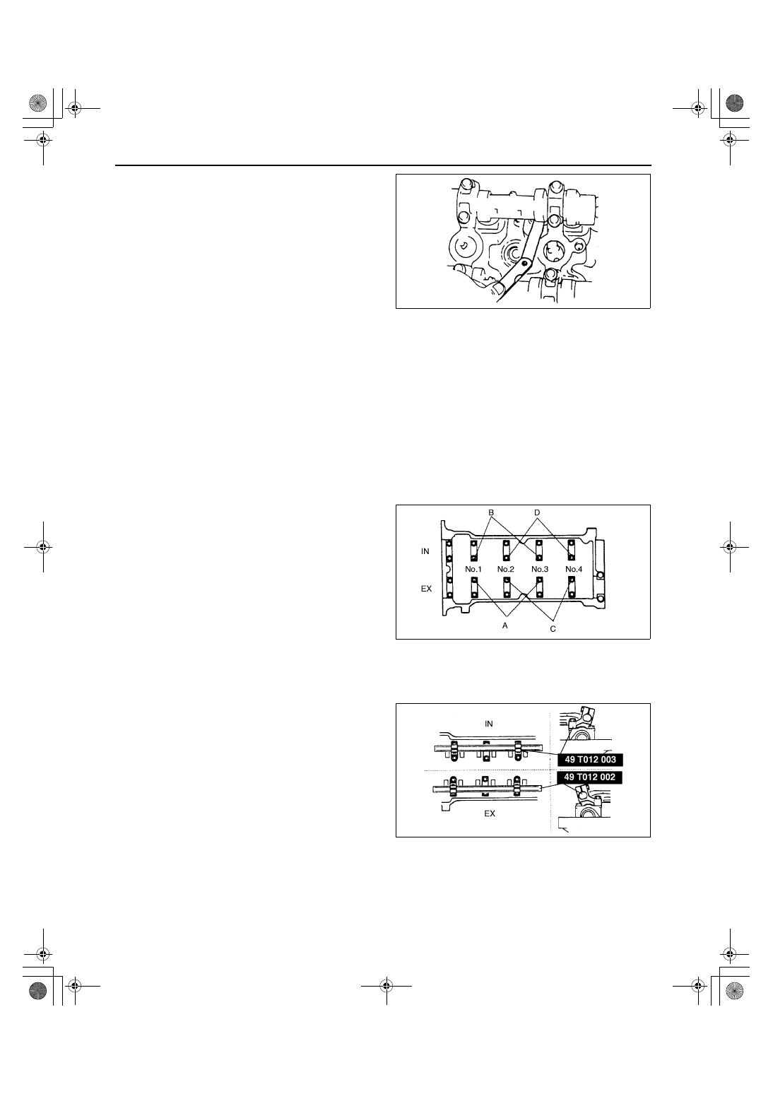
— A: For EX side No.1, 2, 3 cylinder 

adjustment shim removal.

— B: For IN side No.1, 2, 3 cylinder 

adjustment shim removal.

— C: For EX side No.2, 3, 4 cylinder 

adjustment shim removal.

— D: For IN side No.2, 3, 4 cylinder 

adjustment shim removal.

For EX side No.2, 3 cylinder adjustment shim removal, remove either bolt A or C.

For IN side No.2, 3 cylinder adjustment shim removal, remove either bolt B or D.

3. Install the SSTs on the camshaft using the 

camshaft cap bolt holes.

X3U110WA8

X3U110WA9

X3U110WAA

1712-1U-01G(01-10A).fm  6 ページ  2001年6月29日 金曜日 午前9時36分

MECHANICAL [ZM]

01–10A–7

01–10A

Tightening torque

11.3—14.2 N·m {115—145 kgf·cm, 100—125 

in·lbf}

4. Align the marks on the SSTs (shaft and shaft 

clamp).

5. Tighten bolts A to secure the SST (shaft).

6. Face the SST (body) toward the center of the 

cylinder head, and mount it on the SST (shaft) at 
the point of the adjustment shim to be replaced.

7. Face the notch of the tappet so that a fine 

screwdriver can be inserted.

8. Set the SST on the tappet by its notch.

9. Tighten bolt B to secure the SST (body).

Caution

••••

Cylinder head can be damaged when the 
tappet is pressed down.

10. Tighten bolt C, and press down the tappet.

X3U110WAB

X3U110WAC

X3U110WAD

X3U110WAE

X3U110WAF

1712-1U-01G(01-10A).fm  7 ページ  2001年6月29日 金曜日 午前9時36分

MECHANICAL [ZM]

01–10A–8

11. Using a fine screwdriver, pry up the adjustment 

shim through the notch on the tappet. Remove 
the shim using a magnet.

12. Select proper adjustment shim.

New adjustment shim

= Removed shim thickness + Measured 

valve clearance - Standard valve clearance 
(0.28 mm {0.011 in})

13. Push the selected shim into the tappet.
14. Loosen bolt C to allow the tappet to move up.
15. Loosen bolt B and remove the SST (body).
16. Remove the SSTs and tighten the camshaft cap 

bolts.

Tightening torque

11.3—14.2 N·m {115—145 kgf·cm, 100—125 in·lbf}

17. Inspect the valve clearance. (See 01–10A–5 VALVE CLEARANCE INSPECTION [ZM].)

End Of Sie

COMPRESSION INSPECTION [ZM]

A3U011002000W05

Warning

••••

When the engine and the oil are hot, they can cause severe burns. Be careful not to burn yourself 
during removal/installation of each component.

1. Verify that the battery is fully charged.

Recharge it if necessary. (See 01–17–1 Battery.)

2. Warm up the engine to the normal operating temperature.
3. Stop the engine and allow it to cool off for about 10 min.
4. Perform “Fuel Line Safety Procedure”. Leave the fuel pump relay removed. (See 01–14–4 BEFORE REPAIR 

PROCEDURE.)

5. Remove the ignition coils. (See 01–18–1 IGNITION COIL REMOVAL/INSTALLATION.)
6. Remove the spark plugs.
7. Connect a compression gauge into the No.1 spark plug hole.
8. Fully depress the accelerator pedal and crank the engine.
9. Note the maximum gauge reading.

10. Inspect each cylinder as below.

If the compression in one or more cylinders is low or the compression difference between cylinders 
exceeds the maximum, pour a small amount of clean engine oil into the cylinder and reinspect the 
compression.
— If the compression increases, the piston, the piston rings, or cylinder wall may be worn and overhaul is 

required.

— If the compression stays low, a valve may be stuck or improperly seated and overhaul is required.
— If the compression in adjacent cylinders stays low, the cylinder head gasket may be damaged or the 

cylinder head distorted and overhaul is required.

Compression

kPa {kgf/cm

2

, psi} [rpm]

1. Disconnect the compression gauge.
2. Install the spark plugs.

Tightening torque

15—22 N·m {1.5—2.3 kgf·m, 11—16 ft·lbf}

3. Install the ignition coils.
4. Install the fuel pump relay.

X3U110WAG

Item

Engine type

ZM

Standard

1,373 {14.0, 199} [300]

Minimum

981 {10.0, 142} [300]

Maximum difference 
between cylinders

196 {2.0, 28}

1712-1U-01G(01-10A).fm  8 ページ  2001年6月29日 金曜日 午前9時36分

MECHANICAL [ZM]

01–10A–9

01–10A

End Of Sie

TIMING BELT REMOVAL/INSTALLATION [ZM]

A3U011012040W02

1. Disconnect the negative battery cable.
2. Remove the CMP sensor. (See 01–40A–35 CAMSHAFT POSITION (CMP) SENSOR REMOVAL/

INSTALLATION [ZM].)

3. Remove the ignition coils. (See 01–18–1 IGNITION COIL REMOVAL/INSTALLATION.)
4. Remove the drive belt. (See 01–10A–4 DRIVE BELT ADJUSTMENT [ZM].)
5. Remove in the order indicated in the table.
6. Install in the reverse order of removal.
7. Inspect the air gap. (See 01–40A–32 Air Gap Inspection.)
8. Adjust the drive belt deflection/tension. (See 01–10A–4 DRIVE BELT ADJUSTMENT [ZM].)
9. Start the engine and:

(1) Inspect the pulleys and drive belt for runout and contact.
(2) Inspect the ignition timing. (See 01–10A–25 Ignition Timing Inspection.)

.

X3U110WAH

1

Crankshaft pulley

2

Plate

3

Water pump pulley

4

Cylinder head cover
(See 01–10A–13 Cylinder Head Cover Installation 
Note)

5

No.3 engine mount
(See 01–10A–10 No.3 Engine Mount Removal 
Note)
(See 01–10A–13 No.3 Engine Mount Installation 
Note)

6

Timing belt cover

7

Pulley lock bolt
(See 01–10A–10 Pulley Lock Bolt Removal/
Installation Note)

8

Pulley boss

9

Timing belt
(See 01–10A–10 Timing Belt Removal Note)
(See 01–10A–11 Timing Belt Installation Note)

10

Tensioner, tensioner spring
(See 01–10A–11 Tensioner, Tensioner Spring 
Installation Note)

11

Idler

1712-1U-01G(01-10A).fm  9 ページ  2001年6月29日 金曜日 午前9時36分


Content   ..  116  117  118  119   ..