Mazda Protege 5. Manual - part 105
SYMPTOM TROUBLESHOOTING [ENGINE CONTROL SYSTEM (FS)]
01–03B–13
01–03B
NO.1 MELTING OF MAIN OR OTHER FUSES [FS]
A3U010318881W06
End Of Sie
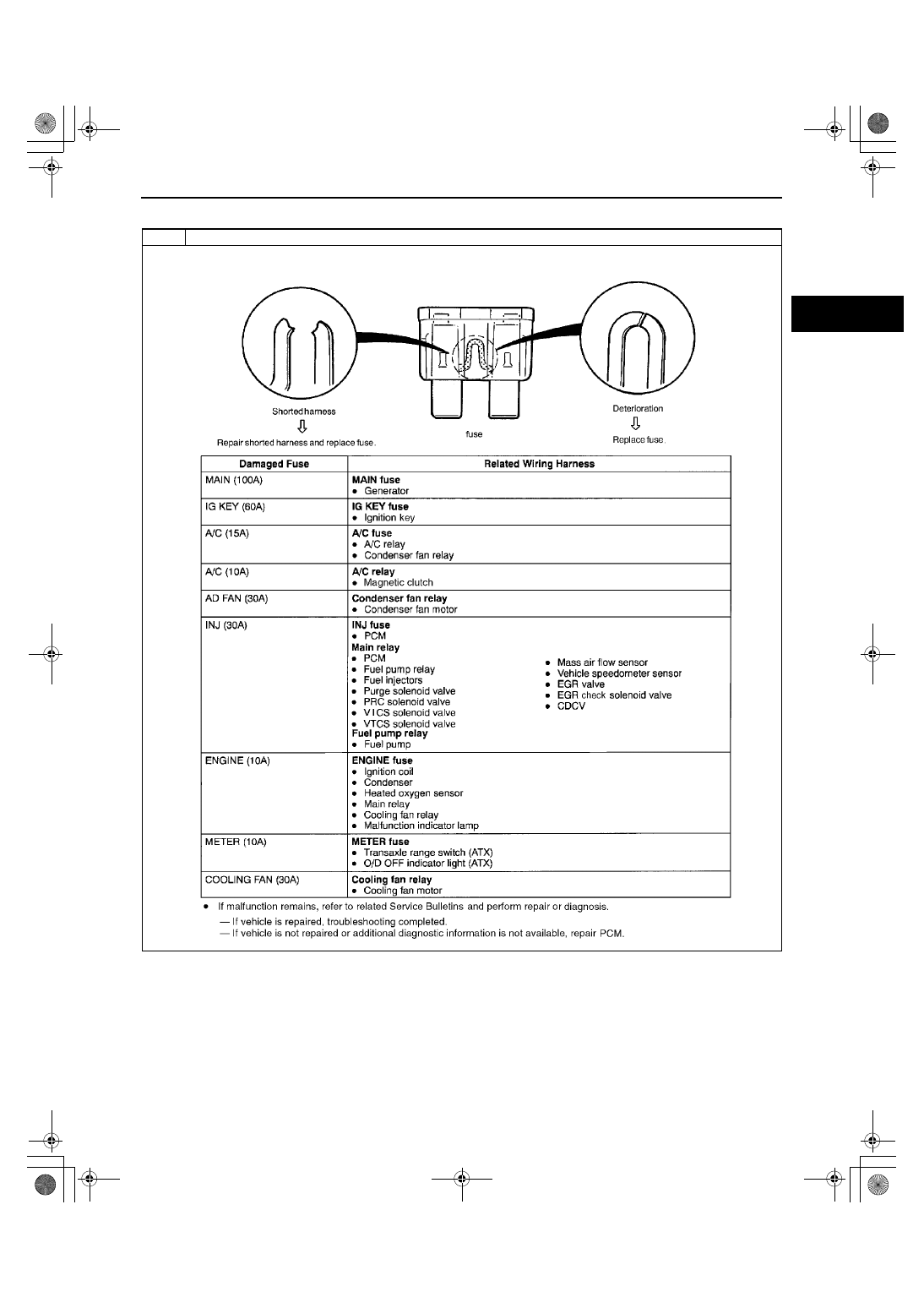
1
Melting of main or other fuses
[TROUBLESHOOTING HINTS]
Inspection condition of fuse.
1712-1U-01G(01-03B).fm 13 ページ 2001年6月29日 金曜日 午前9時33分