Mazda Protege 5. Manual - part 90


  Index      Mazda     Mazda Protege 5 - service repair manual 2002 year


Search            


Content   ..  88  89  90  91   ..


Mazda Protege 5. Manual - part 90


SYMPTOM TROUBLESHOOTING [ENGINE CONTROL SYSTEM (ZM)]

01–03A–13

01–03A

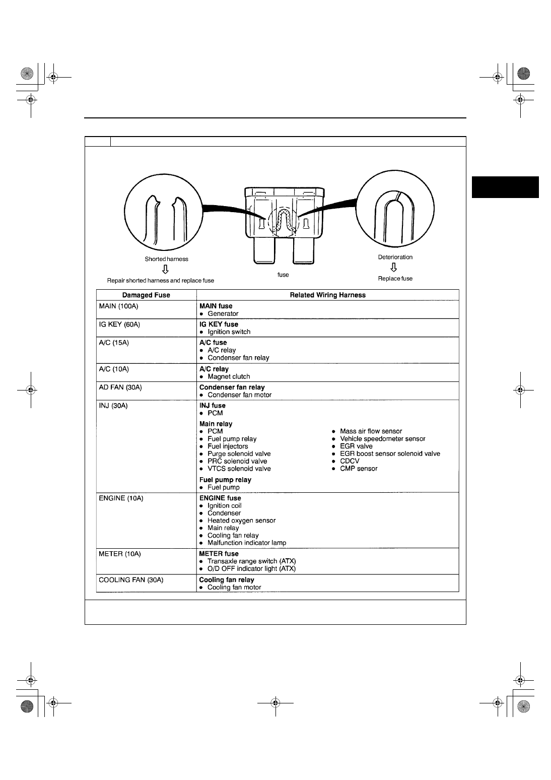
NO.1 MELTING OF MAIN OR OTHER FUSES [ZM]

A3U010318881W43

End Of Sie

1

Melting of main or other fuses

[TROUBLESHOOTING HINTS]
Inspect condition of fuse.

If malfunction remains, refer to related Service Bulletins and perform repair or diagnosis.
— If vehicle is repaired, troubleshooting completed.
— If vehicle is not repaired or additional diagnostic information is not available, replace PCM.

1712-1U-01G(01-03A).fm  13 ページ  2001年6月29日 金曜日 午後4時45分

SYMPTOM TROUBLESHOOTING [ENGINE CONTROL SYSTEM (ZM)]

01–03A–14

NO.2 MIL ILLUMINATES [ZM]

A3U010318881W44

Diagnostic procedure

End Of Sie

NO.3 WILL NOT CRANK [ZM]

A3U010318881W45

Diagnostic procedure

2

Mil illuminates

DESCRIPTION

MIL is illuminated incorrectly.

POSSIBLE 

CAUSE

PCM illuminates for emission-related concern (DTC are stored in PCM)

Short to GND circuit between MIL (located on instrument cluster) and PCM

Note

If MIL blinks at steady rate, misfire condition could possibly exist.

STEP

INSPECTION

ACTION

1

Connect WDS or equivalent to DLC-2.

Turn ignition key to ON.

Retrieve any DTC.

Is “DTC” displayed?

Yes

DTC is displayed:

Go to appropriate DTC test.

No

No DTC is displayed:

Inspect for short to GND circuit between MIL (located on 
instrument cluster) and PCM terminal 2.

2

Verify test results.
— If okay, return to diagnostic index to service any additional symptoms.
— If malfunction remains, inspect related Service Bulletins and perform repair or diagnosis.

If vehicle is repaired, troubleshooting is completed.

If vehicle is not repaired or additional diagnostic information is not available, replace PCM.

3

Will not crank

DESCRIPTION

Starter does not work.

POSSIBLE 

CAUSE

Open starter circuit between ignition switch and starter

Transaxle range switch malfunction (ATX)

Transaxle range switch misadjustment (ATX)

Starter interlock switch malfunction (MTX)

Starter malfunction

Seized/hydrolocked engine, flywheel or drive plate

STEP

INSPECTION

ACTION

1

Inspect for following:
— Battery connection
— Battery condition
— Transaxle is in Park or Neutral. (ATX)
— Clutch is fully depressed. (MTX)
— Fuses

Are all items okay?

Yes

Go to next step.

No

Service as necessary.
Repeat Step 1.

2

Is clicking sound heard from starter when 
ignition switch is turned to START?

Yes

Go to next step.

No

Go to Step 4.

3

Inspect starting system.
(See 01–19–2 STARTER INSPECTION.)

Is starting system okay?

Yes

Inspect for seized/hydrolocked engine, flywheel or drive 
plate.

No

Repair or replace components as required.

4

Do any other electrical accessories work?

Yes

Go to next step.

No

Inspect charging system.
(See 01–17–1 BATTERY INSPECTION.)
(See 01–17–3 GENERATOR INSPECTION.)

5

Note

Following test should be performed on 
ATX only. For MTX, go to next step.

Inspect adjustment of transaxle range 
switch.

Is transaxle range switch adjusted properly?

Yes

Go to next step.

No

Inspect for open circuit between transaxle range switch and 
PCM terminal 64 or starter.

1712-1U-01G(01-03A).fm  14 ページ  2001年6月29日 金曜日 午後4時45分

SYMPTOM TROUBLESHOOTING [ENGINE CONTROL SYSTEM (ZM)]

01–03A–15

01–03A

End Of Sie

NO.4 HARD TO START/LONG CRANK/ERRATIC START/ERRATIC CRANK [ZM]

A3U010318881W46

6

Connect WDS or equivalent to DLC-2.

Turn ignition switch on.

Retrieve any DTC.

Is “DTC” displayed?

Yes

DTC is displayed:

Go to appropriate DTC test.

Communication error message is displayed:

Inspect for following:
— Open circuit between main relay and PCM terminal 

71 or 97

— Open main relay GND circuit
— Main relay is stuck open
— Open or poor GND circuit (PCM terminal 24, 51, 76, 

77 or 103)

— Poor connection of vehicle body GND

No

No DTC is displayed:

Inspect following:
— START circuit in ignition switch
— Open circuit between ignition switch and starter
— Starter interlock switch (MTX)

7

Verify test results.
— If okay, return to diagnostic index to service any additional symptoms.
— If malfunction remains, refer to related Service Bulletins and perform repair or diagnosis.

If vehicle is repaired, troubleshooting completed.

If vehicle is not repaired or additional diagnostic information is not available, replace PCM.

STEP

INSPECTION

ACTION

4

Hard to start/long crank/erratic start/erratic crank

DESCRIPTION

Starter cranks engine at normal speed but engine requires excessive cranking time before start.

Battery is in normal condition.

POSSIBLE 

CAUSE

Spark leakage from high-tension leads

Vacuum leakage

Poor fuel quality

Starting system malfunction

Spark plug malfunction

Air leakage from intake-air system

Erratic signal from CKP sensor

Erratic signal from CMP sensor

Air cleaner restriction

IAC valve malfunction

PCV valve malfunction

Inadequate fuel pressure

Purge solenoid valve malfunction

MAF sensor contamination

Restriction in exhaust system

EGR valve malfunction

Pressure regulator control (PRC) system malfunction

Warning
The following troubleshooting flowchart contains fuel system diagnosis and repair procedures. 
Read following warnings before performing fuel system services:

••••

Fuel vapor is hazardous. It can easily ignite, causing serious injury and damage. Always keep 
sparks and flames away from fuel.

••••

Fuel line spills and leakage are dangerous. Fuel can ignite and cause serious injuries or 
death and damage. Fuel can also irritate skin and eyes. To prevent this, always complete 
“BEFORE REPAIR PROCEDURE” and “AFTER REPAIR PROCEDURE” described in this 
manual.
(See 01–14–4 BEFORE REPAIR PROCEDURE)
(See 01–14–5 AFTER REPAIR PROCEDURE)

1712-1U-01G(01-03A).fm  15 ページ  2001年6月29日 金曜日 午後4時45分

SYMPTOM TROUBLESHOOTING [ENGINE CONTROL SYSTEM (ZM)]

01–03A–16

Diagnostic procedure

STEP

INSPECTION

ACTION

1

Inspect for following:
— Vacuum leakage
— Fuel quality (e.g. proper octane, 

contamination, winter/summer blend)

— Loose bands on intake-air system
— Cracks on intake-air system parts
— Air cleaner restriction

Are all items okay?

Yes

Go to next step.

No

Service as necessary.

2

Connect WDS or equivalent to DLC-2.

Turn ignition switch on.

Retrieve any DTC.

Is “DTC” displayed?

Yes

DTC is displayed:

Go to appropriate DTC test.

No

No DTC is displayed:

Go to next step.

3

Is engine overheating?

Yes

Go to symptom troubleshooting “NO.17 COOLING 
SYSTEM CONCERNS — OVERHEATING [ZM]”.

No

Go to next step.

4

Inspect for cracks on high-tension leads.

Are there any cracks on high-tension leads?

Yes

Repair suspected high-tension leads.

No

Go to next step.

5

Inspect condition of spark plugs.

Is spark plug wet, covered with carbon or 
grayish white?

Yes

Spark plug is wet or covered with carbon:

Inspect for fuel leakage from fuel injector.

Spark plug is grayish white:

Inspect for clogged fuel injector.

No

Install spark plugs on original cylinders.
Go to next step.

6

Visually inspect CKP sensor and teeth of 
crankshaft pulley.

Is CKP sensor and teeth of crankshaft pulley 
okay?

Yes

Go to next step.

No

Replace malfunctioning parts.

7

Measure gap between CKP sensor and teeth 
of crankshaft pulley.

Specification 
0.5—1.5 mm {0.020—0.59 in}

Is gap within specification?

Yes

Go to next step.

No

Adjust CKP sensor.

8

Remove PCV valve and inspect PCV valve.

Does PCV valve rattle?

Yes

Go to next step.

No

Replace PCV valve.

9

Install fuel pressure gauge between fuel filter 
and fuel distributor.

Connect jumper wire between F/P terminal at 
DLC in engine compartment and chassis 
GND.
(See 01–14–5 AFTER REPAIR 
PROCEDURE.)

Turn ignition switch on.

Is fuel line pressure correct?

Fuel line pressure
270—310 kPa {2.7—3.2 kgf/cm

2

, 39—45 psi}

Yes

Go to next step.

No

Zero or low:

Inspect fuel pump circuit.

Inspect for open fuel pump relief valve.

Inspect for fuel leakage inside pressure regulator.

Inspect for clogged main fuel line.

Inspect PRC solenoid valve and related vacuum hose 
and harness.

High

Inspect pressure regulator for high pressure cause.

Inspect for clogged fuel return line.

10

Is fuel line pressure held after ignition switch 
is turned off?
(See 01–14–28 PRESSURE REGULATOR 
INSPECTION.)

Yes

Go to next step.

No

Inspect pressure regulator diaphragm condition.

If condition is okay, inspect fuel injector.

If condition is not okay, replace pressure regulator.

11

Disconnect vacuum hose from pressure 
regulator and plug the hose.

Start engine.

Does fuel line pressure remain within 

±±±±

20 

kPa {0.21 kgf/cm

2

, 3 psi} while driving 

vehicle?

Yes

Go to next step.

No

Inspect for clogged fuel filter.

1712-1U-01G(01-03A).fm  16 ページ  2001年6月29日 金曜日 午後4時45分


Content   ..  88  89  90  91   ..