Mazda Protege 5. Manual - part 78
ON-BOARD DIAGNOSTIC [ENGINE CONTROL SYSTEM (FS)]
01–02B–132
End Of Sie
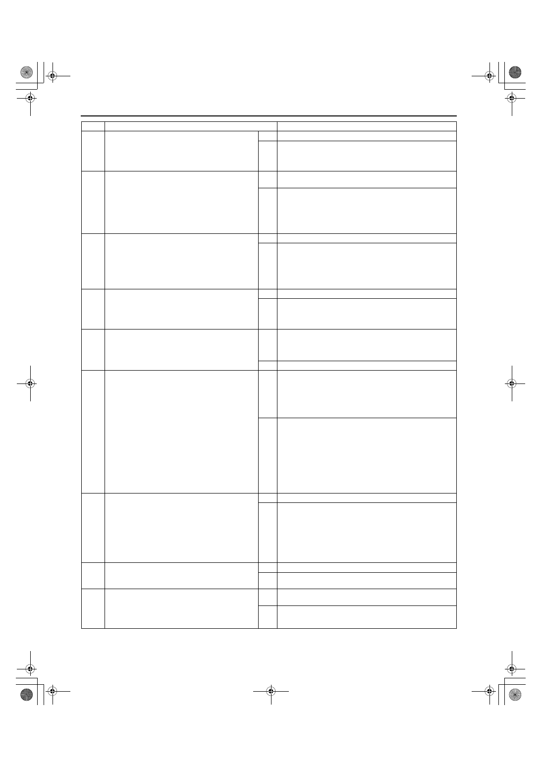
4
INSPECT FOR OPERATION SOUND OF CDCV
•
Perform CDCV inspection.
(See 01–16–10 CANISTER DRAIN CUT
VALVE (CDCV) INSPECTION.)
•
Is CDCV okay?
Yes Go to next step.
No
Replace it if necessary, then go to Step 9.
5
INSPECT PURGE SOLENOID VALVE
•
Disconnect vacuum hose that connects to
intake manifold from purge solenoid valve.
•
Connect vacuum pump to purge solenoid
valve.
•
Pump vacuum several times and wait a few
seconds.
•
Does vacuum hold?
Yes Disconnect vacuum pump and connect vacuum hose to
purge solenoid valve. Go to next step.
No
Inspect purge solenoid valve and related harness. Replace
it if necessary, then go to Step 9.
6
INSPECT CHARCOAL CANISTER FOR
CLOGGING
•
Remove charcoal canister and inspect for
clogging.
(See 01–16–9 CHARCOAL CANISTER
INSPECTION.)
•
Is it okay?
Yes Go to next step.
No
Replace charcoal canister, then go to Step 9.
7
INSPECT FUEL TANK PRESSURE SENSOR
•
Inspect fuel tank pressure sensor.
(See 01–40B–40 FUEL TANK PRESSURE
SENSOR INSPECTION [FS].)
•
Is it okay?
Yes Go to next step.
No
Replace fuel tank pressure sensor, then go to Step 9.
8
INSPECT AIR FILTER FOR CLOGGING
•
Remove and inspect air filter connected to
CDCV for clogging.
•
Is it okay?
Yes Inspect for clogging in following area:
•
From charcoal canister to CDCV
•
Drain passage including check valve
— Repair or replace faulty area, then go to next step.
No
Repair or replace air filter, then go to next step.
9
VERIFY MONITORING CONDITION FOR
EVAPORATIVE SYSTEM TEST
•
Make sure to reconnect all disconnected
connectors.
•
Turn ignition key to ON (Engine OFF).
•
Clear DTC from memory using WDS or
equivalent.
•
Verify that following conditions are met.
— BARO: 69.7 kPa {523 mmHg, 20.5 inHg}
or higher
— ECT: –10.0—20.0
°°°°
C {14.0—68.0
°°°°
F} [at
barometric pressure 69.7 kPa {523 mmHg,
20.5 inHg}]
— IAT: –10—55
°°°°
C {50—131
°°°°
F}
— Fuel tank level: 15—85%
•
Is there any condition out of specification?
Yes Take corrective action (e.g. cool down engine), then repeat
this step.
Note
•
Readings need to be in the indicated ranges to
perform Drive Mode 4.
No
Go to next step.
10
MONITOR EVAP SYSTEM BY DRIVE MODE 4
•
Run Drive Mode 4.
(See 01–02B–12 Mode 4 (EVAP system repair
verification drive mode).)
•
Stop vehicle and access ON BOARD SYSTEM
READINESS TESTS to inspect Drive Mode
completion status.
•
Has EVAPORATIVE PURGE SYSTEM been
monitored?
Yes Go to next step.
No
Go back to Step 9.
11
VERIFY TROUBLESHOOTING OF DTC P1450
COMPLETED
•
Is pending code of same DTC present?
Yes Replace PCM, then go to next step.
No
Go to next step.
12
VERIFY AFTER REPAIR PROCEDURE
•
Perform “After Repair Procedure”.
(See 01–02B–9 AFTER REPAIR
PROCEDURE [FS].)
•
Is there any DTC present?
Yes Go to applicable DTC inspection.
(See 01–02B–15 DTC TABLE [FS].)
No
Troubleshooting completed.
STEP
INSPECTION
ACTION
1712-1U-01G(01-02B).fm 132 ページ 2001年6月29日 金曜日 午後3時24分