Mazda Protege 5. Manual - part 73
ON-BOARD DIAGNOSTIC [ENGINE CONTROL SYSTEM (FS)]
01–02B–112
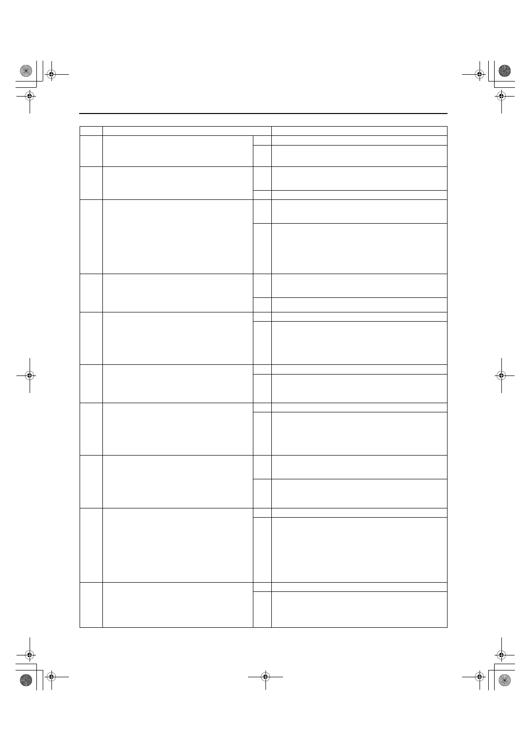
Diagnostic procedure
STEP
INSPECTION
ACTION
1
VERIFY FREEZE FRAME DATA HAS BEEN
RECORDED
•
Has FREEZE FRAME PID DATA been
recorded?
Yes Go to next step.
No
Record FREEZE FRAME PID DATA on repair order, then
go to next step.
2
VERIFY RELATED REPAIR INFORMATION
AVAILABILITY
•
Check for related Service Bulletins availability.
•
Is any related repair information available?
Yes Perform repair or diagnosis according to available repair
information.
•
If vehicle is not repaired, go to next step.
No
Go to next step.
3
VERIFY CURRENT INPUT SIGNAL STATUS-IS
CONCERN INTERMITTENT OR CONSTANT
•
Connect WDS or equivalent to DLC-2.
•
Start engine.
•
Access VS PID using WDS or equivalent.
— Vehicle speed 20 km/h {12.4 mph}: 20km/
h {12.4 mph}
— Vehicle speed 40 km/h {24.8 mph}: 40km/
h {24.8 mph}
•
Are PID readings within specification?
Yes Go to intermittent concern troubleshooting procedure.
(See 01–03B–4 INTERMITTENT CONCERN
TROUBLESHOOTING [FS].)
No
Go to next step.
4
CHECK INPUT/OUTPUT CHECK MODE
•
Turn ignition key to ON (engine OFF).
•
Is instrument cluster DTCs 10 or 12 detected?
(See 09–22–5 INSTRUMENT CLUSTER
INPUT/OUTPUT CHECK MODE.).
Yes DTC 10 and/or 12 displayed: Inspect instrument cluster.
(See 09–22–5 INSTRUMENT CLUSTER INPUT/OUTPUT
CHECK MODE.)
No
Go to next step.
5
INSPECT PCM CONNECTOR FOR POOR
CONNECTION
•
Turn ignition key to OFF.
•
Disconnect PCM connector.
•
Check for poor connection (damaged/pulled-
out terminals, corrosion, etc.).
•
Are terminals okay?
Yes Go to next step.
No
Repair or replace pin or connector, then go to Step 11.
6
INSPECT CRUISE CONTROL MODULE
CONNECTOR
•
Disconnect cruise control module connector.
•
Inspect for bent terminals.
•
Are terminals okay?
Yes Go to next step.
No
Repair terminals, then go to Step 11.
7
INSPECT INSTRUMENT CLUSTER
CONNECTOR FOR POOR CONNECTION
•
Turn ignition key to OFF.
•
Disconnect instrument cluster connector.
•
Check for poor connections (damaged/pulled-
out terminals, corrosion, etc.).
•
Are terminals okay?
Yes Go to next step.
No
Repair or replace terminals, then go to Step 11.
8
INSPECT VOLTAGE
•
Connect PCM connector.
•
Turn ignition key to ON (engine OFF).
•
Measure voltage at instrument cluster terminal
3O (harness-side).
•
Is there 5 V at instrument cluster terminal 3O
(harness-side)?
Yes Replace instrument cluster, then go to Step 11.
(See 09–22–3 INSTRUMENT CLUSTER REMOVAL/
INSTALLATION.)
No
Go to next step.
9
INSPECT INSTRUMENT CLUSTER CIRCUIT
FOR OPEN CIRCUIT
•
Turn ignition key to OFF.
•
Connect breakout box with PCM connector
disconnected.
•
Turn ignition key to ON (engine OFF).
•
Check for continuity between instrument
cluster terminal 3O (harness-side) and
breakout box terminal 58.
•
Is there continuity?
Yes Go to next step.
No
Repair or replace harness, then go to Step 11.
10
INSPECT INSTRUMENT CLUSTER CIRCUIT
FOR SHORT TO GROUND
•
Check for continuity between instrument
cluster terminal 3O (harness-side) and body
ground.
•
Is there continuity?
Yes Repair or replace harness, then go to next step.
No
Replace instrument cluster, then go to next step.
1712-1U-01G(01-02B).fm 112 ページ 2001年6月29日 金曜日 午後3時24分