Mazda Protege 5. Manual - part 61
ON-BOARD DIAGNOSTIC [ENGINE CONTROL SYSTEM (FS)]
01–02B–64
Diagnostic procedure
End Of Sie
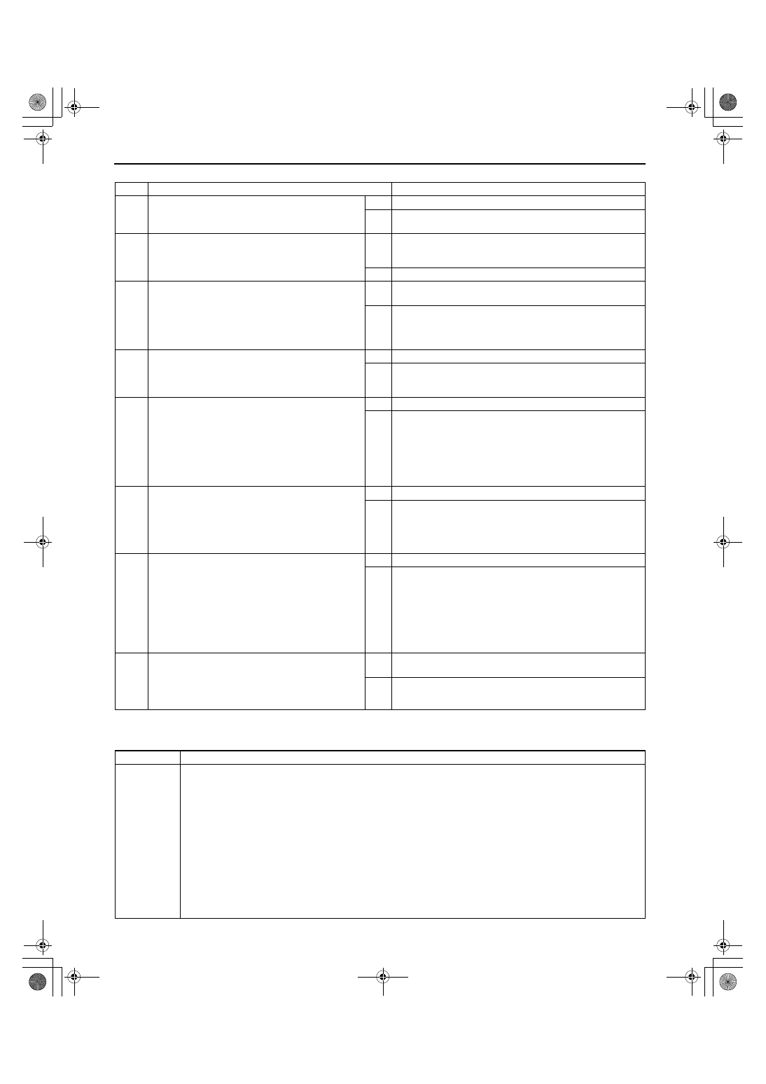
DTC P0140 [FS]
A3U010201084W26
STEP
INSPECTION
ACTION
1
VERIFY FREEZE FRAME DATA HAS BEEN
RECORDED
•
Has FREEZE FRAME DATA been recorded?
Yes Go to next step.
No
Record FREEZE FRAME DATA on repair order, then go to
next step.
2
VERIFY RELATED REPAIR INFORMATION
AVAILABILITY
•
Check for related Service Bulletins availability.
•
Is any related repair information available?
Yes Perform repair or diagnosis according to available repair
information.
•
If vehicle is not repaired, go to next step.
No
Go to next step.
3
VERIFY RELATED PENDING OR STORED
DTCS
•
Turn ignition key to OFF, then Start engine.
•
Verify pending codes or stored DTCs using
WDS or equivalent.
•
Is other DTC present?
Yes Go to appropriate DTC troubleshooting procedures.
(See 01–02B–15 DTC TABLE [FS].)
No
Go to next step.
4
IDENTIFY TRIGGER DTC FOR FREEZE FRAME
DATA
•
Is DTC P0138 on FREEZE FRAME DATA?
Yes Go to next step.
No
Go to troubleshooting procedures for DTC on FREEZE
FRAME DATA.
(See 01–02B–15 DTC TABLE [FS].)
5
INSPECT HO2S (REAR) SIGNAL CIRCUIT FOR
SHORT TO POWER SUPPLY CIRCUIT
•
Turn ignition key to OFF.
•
Disconnect HO2S (rear) connector.
•
Turn ignition key to ON (Engine OFF).
•
Measure voltage between HO2S (rear)
terminal A (harness-side) and body ground.
•
Is any voltage reading?
Yes Replace short to power supply circuit, then go to Step 7.
No
Go to next step.
6
VERIFY CURRENT INPUT SIGNAL STATUS
•
Start engine.
•
Access O2S12 PID using WDS or equivalent.
•
Verify PID while racing engine at least 10
times (in neutral position).
•
Does PID reading stay above 0.45 V?
Yes Replace HO2S (rear), then go to next step.
No
Go to next step.
7
VERIFY TROUBLESHOOTING OF DTC P0138
COMPLETED
•
Make sure to reconnect all disconnected
connectors.
•
Turn ignition key to ON (Engine OFF).
•
Clear DTC from memory using WDS or
equivalent.
•
Run OBD-II DRIVE MODE 1 and 3.
•
Is PENDING CODE of same DTC present?
Yes Replace PCM, then go to next step.
No
Go to next step.
8
VERIFY AFTER REPAIR PROCEDURE
•
Perform “After Repair Procedure”.
(See 01–02B–9 AFTER REPAIR
PROCEDURE [FS].)
•
Is there any DTC present?
Yes Go to applicable DTC inspection.
(See 01–02B–15 DTC TABLE [FS].)
No
Troubleshooting completed.
DTC P0140
HO2S (rear) circuit no activity detected
DETECTION
CONDITION
•
PCM monitors input voltage from HO2S (rear) when the following monitoring conditions are met. If input
voltage from sensor never exceed 0.55 V for 30 seconds, PCM determines that sensor circuit is not
activated.
MONITORING CONDITIONS
— Drive mode 3
— Following conditions are met:
•
Engine speed is above 1,500 rpm.
•
Engine coolant temperature is above 70
°°°°
C {158
°°°°
F}.
Diagnostic support note
•
This is a continuous monitor (CCM).
•
MIL illuminates if PCM detects the above malfunction condition in two consecutive drive cycles.
•
PENDING CODE is available if PCM detects the above malfunction condition during first drive cycle.
•
FREEZE FRAME DATA is available.
•
DTC is stored in PCM memory.
1712-1U-01G(01-02B).fm 64 ページ 2001年6月29日 金曜日 午後3時24分