Mazda Protege 5. Manual - part 42


  Index      Mazda     Mazda Protege 5 - service repair manual 2002 year


Search            


Content   ..  40  41  42  43   ..


Mazda Protege 5. Manual - part 42


ON-BOARD DIAGNOSTIC [ENGINE CONTROL SYSTEM (ZM)]

01–02A–134

DTC P1512 [ZM]

A3U010201083W32

Diagnostic procedure

DTC P1512

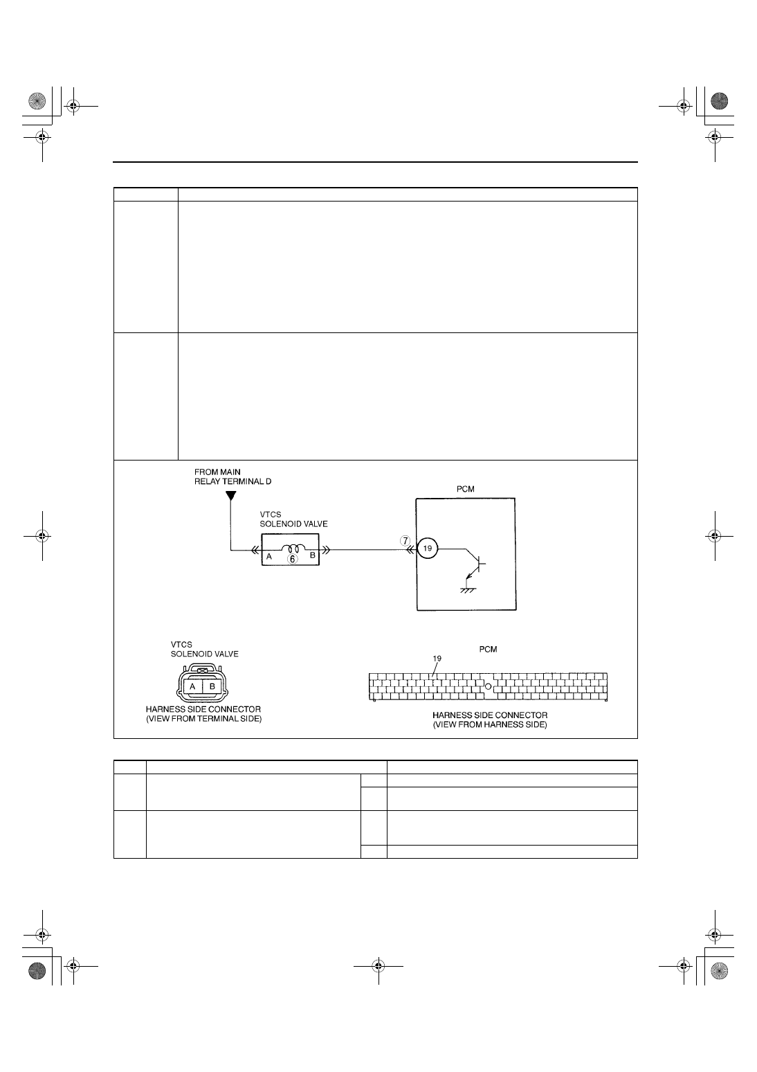
Variable tumble control system (VTCS) shutter valve close stuck

DETECTION 

CONDITION

PCM monitors air flow amount is above 30 g/s {4.0 lb/min} when the following monitoring conditions are 
met. PCM determines that VTCS shutter valve has closed stuck malfunction.

MONITORING CONDITIONS

— Engine speed is above 3,000 rpm.
— Engine coolant temperature is above 80 

°°°°

C {176 

°°°°

F}.

— Throttle valve opening angle is above 75%.

Diagnostic support note

This is a continuous monitor (CCM).

MIL illuminates if PCM detects the above the above malfunction condition in two consecutive drive cycles.

PENDING CODE is available if PCM detects the above malfunction condition during first drive cycle.

FREEZE FRAME DATA is available.

DTC is stored in PCM memory.

POSSIBLE 

CAUSE

ECT sensor malfunction

MAF sensor malfunction

IAT sensor malfunction

EGR boost sensor malfunction

TP sensor malfunction

CKP sensor malfunction

VTCS solenoid valve malfunction

VTCS shutter valve malfunction (stuck closed)

VTCS shutter valve actuator malfunction (stuck closed).

Short to ground circuit between VTCS solenoid valve terminal B and PCM terminal 19

Short to power circuit between VTCS solenoid valve terminal B and PCM terminal 19

PCM malfunction

STEP

INSPECTION

ACTION

1

CHECK FREEZE FRAME DATA HAS BEEN 
RECORDED

Has FREEZE FRAME DATA been recorded?

Yes Go to next step.

No

Record FREEZE FRAME DATA on repair order, then go to 
next step.

2

CHECK RELATED REPAIR INFORMATION 
AVAILABILITY

Check for related Service Bulletins availability.

Is any related repair information available?

Yes Perform repair or diagnosis according to available repair 

information.

If vehicle is not repaired, go to next step.

No

Go to next step.

1712-1U-01G(01-02A).fm  134 ページ  2001年6月29日 金曜日 午後2時20分

ON-BOARD DIAGNOSTIC [ENGINE CONTROL SYSTEM (ZM)]

01–02A–135

01–02A

End Of Sie

DTC P1562 [ZM]

A3U010201083W33

3

CLASSIFY INTERMITTENT CONCERN OR 
CONTINUOUS CONCERN

Clear DTC from PCM memory using WDS or 
equipment.

Verify that following conditions are met.
— ECT: at 20 

°°°°

C {68 

°°°°

F}

Drive vehicle under following conditions:
— Engine speed: above 3,000 rpm
— MAF: below 30 g/s {4.0 lb/min}

Is pending code of same DTC present?

Yes Go to next step.

No

Intermittent concern exists. Go to INTERMITTENT 
CONCERN TROUBLESHOOTING procedure.
(See 01–03A–4 INTERMITTENT CONCERN 
TROUBLESHOOTING [ZM].)

4

VERIFY STORED OTHER DTCS

Verify stored DTCs using WDS or equipment.

Is other DTC present except P1512?

Yes Go to appropriate DTC troubleshooting procedures.

No

Go to next step.

5

INSPECT VTCS SHUTTER VALVE ACTUATOR

Carry out “VTCS operation inspection”
(See 01–03A–58 Variable Tumble Control 
System (VTCS) Inspection.)

Is VTCS shutter valve actuator okay?

Yes Go to next step.

No

Replace VTCS shutter valve actuator, then go to Step 8.

6

INSPECT VTCS SOLENOID VALVE

Carry out “VTCS solenoid valve airflow 
inspection”
(See 01–13A–11 VARIABLE TUMBLE 
CONTROL SYSTEM (VTCS) SOLENOID 
VALVE INSPECTION [ZM].)

Is VTCS solenoid valve okay?

Yes Go to next step.

No

Replace VTCS solenoid valve, then go to Step 8.

7

CHECK PCM FOR POOR CONNECTION

Check for poor connection at PCM terminal 19 
(damaged/pulled-out terminals, corrosion, 
etc.).

Is there malfunction?

Yes Repair terminal, then go to next step.

No

Go to next step.

8

VERIFY TROUBLESHOOTING OF DTC P1512 
COMPLETED

Make sure to reconnect all disconnected 
connectors.

Start engine.

Clear DTC from PCM memory using WDS or 
equipment.

Start engine.

Verify that following conditions are met.
— ECT: at 20 

°°°°

C {68 

°°°°

F}

Drive vehicle under following conditions:
— Engine speed: above 3,000 rpm
— MAF: below 30 g/s {4.0 lb/min}

Is pending code of same DTC present?

Yes Replace PCM, then go to next step.

No

Go to next step.

9

VERIFY AFTER REPAIR PROCEDURE

Perform “After Repair Procedure”.
(See 01–02A–10 AFTER REPAIR 
PROCEDURE [ZM].)

Is there any DTC present?

Yes Go to applicable DTC inspection.

(See 01–02A–15 DTC TABLE [ZM].)

No

Troubleshooting completed.

STEP

INSPECTION

ACTION

DTC P1562

PCM +BB voltage low

DETECTION 

CONDITION

PCM monitors voltage of backup battery positive terminal at PCM terminal 55 after engine is started. If the 
PCM detected battery positive terminal voltage below 2.5 V for 2 seconds, PCM determines that backup 
voltage circuit has malfunction.

Diagnostic support note

This is a continuous monitor (CCM).

MIL illuminates if PCM detects the above malfunction condition during first drive cycle. Therefore, 
PENDING CODE is not available.

FREEZE FRAME DATA is available.

DTC is stored in PCM memory.

POSSIBLE 

CAUSE

Open circuit or short to ground in wiring between battery positive terminal and PCM terminal 55

Poor connection of PCM connector

PCM malfunction

1712-1U-01G(01-02A).fm  135 ページ  2001年6月29日 金曜日 午後2時20分

ON-BOARD DIAGNOSTIC [ENGINE CONTROL SYSTEM (ZM)]

01–02A–136

Diagnostic procedure

DTC P1562

PCM +BB voltage low

STEP

INSPECTION

ACTION

1

VERIFY FREEZE FRAME DATA HAS BEEN 
RECORDED

Has FREEZE FRAME DATA been recorded?

Yes Go to next step.

No

Record FREEZE FRAME DATA on repair order, then go to 
next step.

2

VERIFY RELATED REPAIR INFORMATION 
AVAILABILITY

Check for related Service Bulletins availability.

Is any repair information available?

Yes Perform repair or diagnosis according to available repair 

information.

If vehicle is not repaired, then go to next step.

No

Go to next step.

3

INSPECT MONITOR CIRCUIT FOR SHORT TO 
GROUND

Disconnect both battery cables.

Measure resistance between battery positive 
cable and body ground.

Is resistance more than 500 ohms?

Yes Go to next step.

No

Repair or replace harness between battery positive left 
terminal and PCM terminal 55 for short to ground, then go 
to Step 6.

4

INSPECT PCM CONNECTOR FOR POOR 
CONNECTION

Disconnect PCM connector.

Check for poor connection at terminal 55 
(damaged/pulled-out terminals, corrosion, 
etc.).

Is there malfunction?

Yes Repair terminals, then go to Step 6.

No

Go to next step.

5

INSPECT MONITOR CIRCUIT FOR OPEN 
CIRCUIT

Disconnect battery cables.

Connect breakout box with PCM disconnected.

Check for continuity between battery positive 
cable and breakout box terminal 55.

Is there continuity?

Yes Go to next step.

No

Repair or replace harness for open, then go to next step.

6

VERIFY TROUBLESHOOTING OF DTC P1562 
COMPLETED

Make sure to reconnect all disconnected 
connectors.

Clear DTC using WDS or equivalent.

Turn ignition key to OFF, then start engine.

Is same DTC present?

Yes Replace PCM, then go to next step.

No

Go to next step.

7

VERIFY AFTER REPAIR PROCEDURE

Perform “After Repair Procedure”.
(See 01–02A–10 AFTER REPAIR 
PROCEDURE [ZM].)

Is there any DTC present?

Yes Go to applicable DTC inspection.

(See 01–02A–15 DTC TABLE [ZM].)

No

Troubleshooting completed.

1712-1U-01G(01-02A).fm  136 ページ  2001年6月29日 金曜日 午後2時20分

ON-BOARD DIAGNOSTIC [ENGINE CONTROL SYSTEM (ZM)]

01–02A–137

01–02A

End Of Sie

DTC P1569 [ZM]

A3U010201083W34

Diagnostic procedure

DTC P1569

Variable tumble control system (VTCS) solenoid valve circuit low input

DETECTION 

CONDITION

PCM monitors input voltages from VTCS solenoid valve. If voltage at PCM 19 is low when VTCS solenoid 
valve OFF, PCM determines that VTCS solenoid valve has malfunction.

Diagnostic support note

This is a continuous monitor (CCM).

MIL illuminates if PCM detects the above the above malfunction condition in two consecutive drive cycles.

PENDING CODE is available if PCM detects the above malfunction condition during first drive cycle.

FREEZE FRAME DATA is available.

DTC is stored in PCM memory.

POSSIBLE 

CAUSE

Poor connection of connectors at PCM and/or VTCS solenoid valve

Short to ground in wiring between VTCS solenoid valve terminal B and PCM terminal 19

Open circuit in wiring between main relay terminal D and VTCS solenoid valve terminal A

Open circuit in wiring between VTCS solenoid valve terminal B and PCM terminal 19

VTCS solenoid valve malfunction

PCM malfunction

STEP

INSPECTION

ACTION

1

CHECK FREEZE FRAME DATA HAS BEEN 
RECORDED

Has FREEZE FRAME DATA been recorded?

Yes Go to next step.

No

Record FREEZE FRAME DATA on repair order, then go to 
next step.

2

VERIFY RELATED REPAIR INFORMATION 
AVAILABILITY

Check for related Service Bulletins availability.

Is any related repair information available?

Yes Perform repair or diagnosis according to available repair 

information.

If vehicle is not repaired, go to next step.

No

Go to next step.

3

CLASSIFY INTERMITTENT CONCERN OR 
CONTINUOUS CONCERN

Clear DTC from PCM memory using WDS or 
equipment.

Start engine and warm it up completely.

Is pending code of same DTC present?

Yes Go to next step.

No

Intermittent concern exists. Go to INTERMITTENT 
CONCERN TROUBLESHOOTING procedure.
(See 01–03A–4 INTERMITTENT CONCERN 
TROUBLESHOOTING [ZM].)

1712-1U-01G(01-02A).fm  137 ページ  2001年6月29日 金曜日 午後2時20分


Content   ..  40  41  42  43   ..