Mazda Protege 5. Manual - part 16
ON-BOARD DIAGNOSTIC [ENGINE CONTROL SYSTEM (ZM)]
01–02A–30
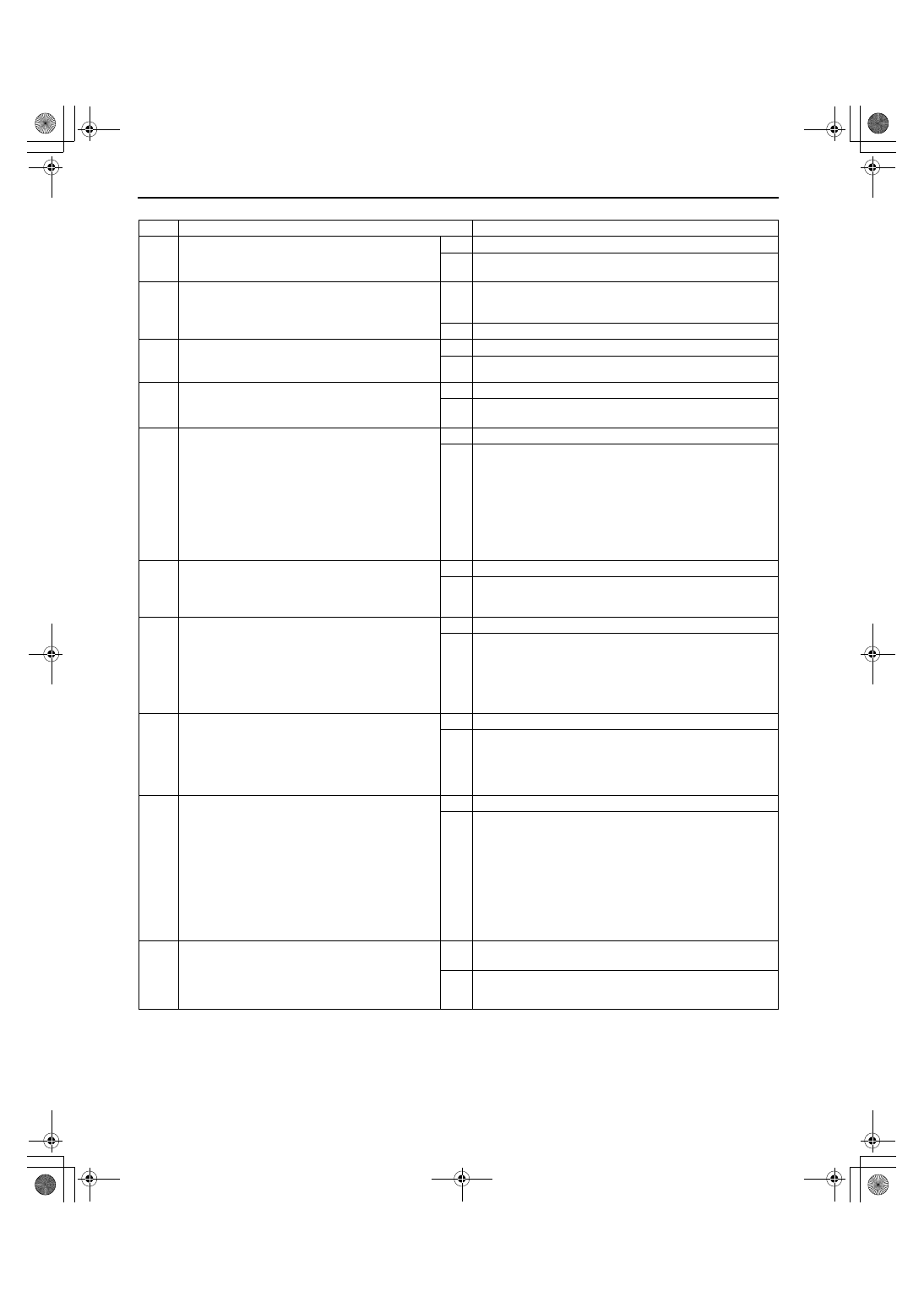
Diagnostic procedure
End Of Sie
STEP
INSPECTION
ACTION
1
VERIFY FREEZE FRAME DATA HAS BEEN
RECORDED
•
Has FREEZE FRAME DATA been recorded?
Yes Go to next step.
No
Record FREEZE FRAME DATA on repair order, then go to
next step.
2
VERIFY RELATED REPAIR INFORMATION
AVAILABILITY
•
Check for related Service Bulletins availability.
•
Is any related repair information available?
Yes Perform repair or diagnosis according to available repair
information.
•
If vehicle is not repaired, go to next step.
No
Go to next step.
3
VERIFY STORED DTC
•
Turn ignition key to OFF then start engine.
•
Has DTC P1487 been stored?
Yes Inspect and repair DTC P1487.
No
Go to next step.
4
IDENTIFY TRIGGER DTC FOR FREEZE FRAME
DATA
•
Is DTC P0106 on FREEZE FRAME DATA?
Yes Go to next step.
No
Go to troubleshooting procedures for DTC on FREEZE
FRAME DATA.
5
INSPECT CONNECTION OF EGR BOOST
SENSING RELATED VACUUM HOSES
•
Inspect the following vacuum hoses for
looseness, damage, improper connection and/
or clogging.
— From EGR boost sensor to EGR boost
sensor solenoid
— From EGR boost sensor solenoid to intake
manifold
•
Are they okay?
Yes Go to next step.
No
Repair or replace vacuum hose, then go to Step 9.
6
INSPECT EGR BOOST SENSOR SOLENOID
AIR FILTER FOR CLOGGING
•
Has EGR boost sensor solenoid air filter been
clogged?
Yes Repair air clogging, then go to Step 9.
No
Go to next step.
7
INSPECT EGR BOOST SENSOR SOLENOID
VALVE FOR WHETHER STUCK OPEN OR
CLOSED
•
Inspect EGR boost sensor solenoid valve.
(See 01–16–17 EGR BOOST SENSOR
SOLENOID VALVE INSPECTION)
•
Is EGR boost sensor solenoid okay?
Yes Go to next step.
No
Replace EGR boost sensor solenoid, then go to Step 9.
8
INSPECT EGR BOOST SENSOR FOR
WHETHER STUCK OPEN OR CLOSED
•
Inspect EGR boost sensor.
(See 01–40A–38 EGR BOOST SENSOR
INSPECTION [ZM])
•
Is EGR boost sensor okay?
Yes Go to next step.
No
Replace EGR boost sensor, then go to next step.
9
VERIFY TROUBLESHOOTING OF DTC P0106
COMPLETED
•
Make sure to reconnect all disconnected
connectors.
•
Turn ignition key to ON (Engine OFF).
•
Clear DTC from memory using WDS or
equivalent.
•
Run OBD-ll DRIVE MODE 1, 2 and 3.
(See 01–02A–11 OBD-II DRIVE MODE [ZM])
•
Stop vehicle.
•
Is same DTC present?
Yes Replace PCM, then go to next step.
No
Go to next step.
10
VERIFY AFTER REPAIR PROCEDURE
•
Perform “After Repair Procedure”.
(See 01–02A–10 AFTER REPAIR
PROCEDURE [ZM].)
•
Is there any DTC present?
Yes Go to applicable DTC inspection.
(See 01–02A–15 DTC TABLE [ZM].)
No
Troubleshooting completed.
1712-1U-01G(01-02A).fm 30 ページ 2001年6月29日 金曜日 午後2時20分