Mazda 5. Manual - part 51


  Index      Mazda     Mazda 5 - service repair manual


Search            


Content   ..  49  50  51  52   ..


Mazda 5. Manual - part 51


05–17–124

AUTOMATIC TRANSAXLE 

Forward Clutch Preinspection
Clutch operation

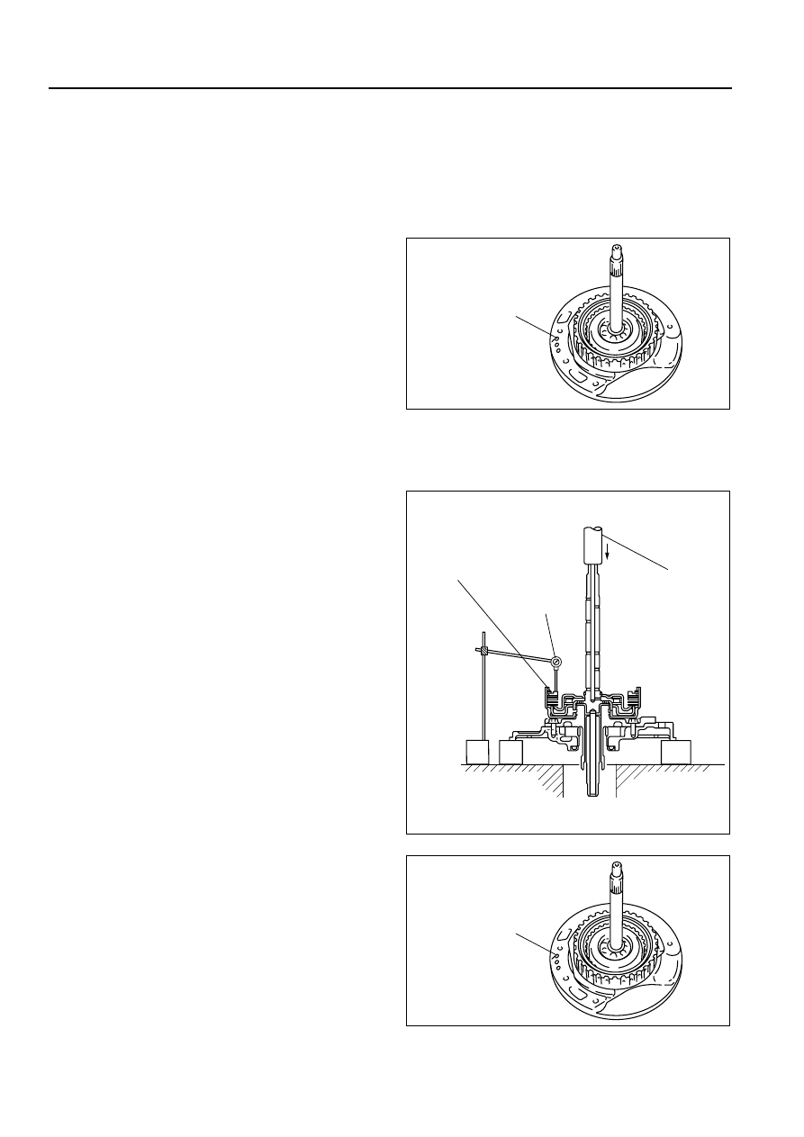
1. Set the forward clutch onto the oil pump.

Caution

• Applying compressed air to the assembled clutch pack for longer than 3 s at a time will damage 

the seal. 
Do not apply compressed air for more than the aforementioned time when testing the system.

2. Inspect the clutch operation by applying 

compressed air through the fluid passages 
shown.

Air pressure

392 kPa {4.0 kgf/cm

2

, 57 psi} max.

3. If not as specified, replace parts as necessary. 

(See 05–17–56 FORWARD CLUTCH 
DISASSEMBLY/ASSEMBLY.)

Clutch clearance

1. Measure the forward clutch clearance.

(1) Install the forward clutch in the oil pump, and set the dial gauge.
(2) Secure the forward clutch by lightly pressing 

down with a press, etc.

(3) Apply compressed air to the part indicated in 

the figure and let the forward clutch piston 
stroke three times.

Air pressure

392—441 kPa {4.0—4.5 kgf/cm

2

, 57—63 psi}

(4) Apply compressed air and operate the 

forward clutch piston. Read the value when 
the indicator of the dial gauge stops.

(5) Release the compressed air and read the dial 

gauge when the forward clutch piston is not 
operating.

(6) Calculate the forward clutch clearance 

according to the following formula:

FORWARD CLUTCH 
FLUID PASSAGE

B3E0517A117

PRESS

DIAL GAUGE

RETAINING PLATE

B3E0517A323

FORWARD CLUTCH 
FLUID PASSAGE

B3E0517A117

AUTOMATIC TRANSAXLE 

05–17–125

05

Step (4) value – Step (5) value = Forward clutch clearance.

(7) Measure the clearances at four locations (90

° 

apart) by following the steps from (3) to (6). 
Verify that the average value is within the 
specification below.

Forward clutch clearance

1.50—1.80 mm {0.059—0.071 in}

2. If not as specified, replace parts as necessary. 

(See 05–17–56 FORWARD CLUTCH 
DISASSEMBLY/ASSEMBLY.)

Clutch Component Preinspection
Clutch operation

1. Set the clutch component onto the end cover.

Caution

• Applying compressed air to the assembled clutch pack for longer than 3 s at a time will damage 

the seal.
Do not apply compressed air for more than the aforementioned time when testing the system.

2. Inspect the clutch operation by applying 

compressed air as shown.

Air Pressure

392 kPa {4.0 kgf/cm

2

, 57 psi} max.

3. If not as specified, replace parts as necessary. 

(See 05–17–60 CLUTCH COMPONENT 
DISASSEMBLY/ASSEMBLY.)

Reverse clutch clearance

1. Measure the reverse clutch clearance.

(1) Install the reverse clutch into the end cover, and set the dial gauge.
(2) Secure the reverse clutch by lightly pressing 

down with a press, etc.

RETAINING
PLATE

CLEARANCE

SNAP RING

B3E0517A324

3-4 CLUTCH

FLUID PASSAGE

REVERSE

CLUTCH FLUID

PASSAGE

B3E0517A325

PLATE

PRESS

RETAINING 
PLATE

DIAL GAUGE

B3E0517A254

05–17–126

AUTOMATIC TRANSAXLE 

(3) Apply compressed air to the part indicated in 

the figure and let the reverse clutch piston 
stroke three times.

Air Pressure

392—441 kPa {4.0—4.5 kgf/cm

2

, 57—63 psi} 

(4) Apply compressed air and operate the 

reverse clutch piston. Read the value when 
the indicator of the dial gauge stops.

(5) Release the compressed air and read the dial 

gauge when the reverse clutch piston is not 
operating.

(6) Calculate the reverse clutch clearance 

according to the following formula: Step (4) value – Step (5) value = Reverse clutch clearance.

(7) Measure the clearances at four locations (90

° 

apart) by following the steps from (3) to (6). 
Verify that the average value is within the 
specification below.

Reverse clutch clearance

1.00—1.30 mm {0.039—0.051 in}

2. If not as specified, replace parts as necessary. 

(See 05–17–60 CLUTCH COMPONENT 
DISASSEMBLY/ASSEMBLY.)

3-4 clutch clearance

1. Measure the 3-4 clutch clearance.

(1) Install the 3-4 clutch in the end cover and set the dial gauge.
(2) Secure the 3-4 clutch by lightly pressing down 

with a press, etc.

(3) Apply compressed air to the part indicated in 

the figure and let the 3-4 clutch piston stroke 
three times.

Air pressure

392—441 kPa {4.0—4.5 kgf/cm

2

, 57—63 psi}

(4) Apply compressed air and operate the 3-4 

clutch piston. Read the value when the 
indicator of the dial gauge stops.

(5) Release the compressed air and read the dial 

gauge when the 3-4 clutch piston is not 
operating.

(6) Calculate the 3-4 clutch clearance according 

to the following formula:
Step (4) value – Step (5) value = 3-4 clutch clearance.

REVERSE CLUTCH
FLUID PASSAGE

B3E0517A255

RETAINING
PLATE

SNAP RING

CLEARANCE

B3E0517A256

DIAL GAUGE

RETAINING
PLATE

PRESS

B3E0517A261

3-4 CLUTCH FLUID PASSAGE

B3E0517A262

AUTOMATIC TRANSAXLE 

05–17–127

05

(7) Measure the clearances at four locations (90

° 

apart) by following the steps from (3) to (6). 
Verify that the average value is within the 
specification below.

3-4 clutch clearance

Drive plate part number: FN11 19 370

1.00—1.30 mm {0.039—0.051 in}

Drive plate part number: FNE1 19 370

1.10—1.40 mm {0.043—0.055 in}

2. If not as specified, replace parts as necessary. 

(See 05–17–60 CLUTCH COMPONENT 
DISASSEMBLY/ASSEMBLY.)

Bushing inner diameter inspection

1. Measure the bushing of the 3-4 clutch hub.

Bushing inner diameter

Standard: 18.000—18.018 mm 

{0.70866—0.70936 in}

Maximum: 18.038 mm {0.71016 in}

2. If not as specified, replace the 3-4 clutch hub. 

(See 05–17–60 CLUTCH COMPONENT 
DISASSEMBLY/ASSEMBLY.)

3. Measure the bushing of the 2-4 brake drum.

Bushing inner diameter

Standard: 55.005—55.030 mm 

{2.16555—2.16653 in}

Maximum: 55.050 mm {2.16732 in}

4. If not as specified, replace the 2-4 brake drum. 

(See 05–17–60 CLUTCH COMPONENT 
DISASSEMBLY/ASSEMBLY.)

Front Internal Gear and One-Way Clutch Component
Preinspection

1. Set the front internal gear and one-way clutch 

component to the one-way clutch inner race. 
Verify that the one-way clutch rotates smoothly 
when turned counterclockwise and locks when 
turned clockwise.

2. If not as specified, replace parts as necessary. 

(See 05–17–68 FRONT INTERNAL GEAR 
ONE-WAY CLUTCH COMPONENT 
DISASSEMBLY/ASSEMBLY.)

Low and Reverse Brake Preinspection
Clutch operation

Caution

• Applying compressed air to the assembled clutch pack for longer than 3 s at a time will damage 

the seal.

SNAP RING

RETAINING PLATE

CLEARANCE

B3E0517A263

BUSHING

B3E0517A326

BUSHING

B3E0517A327

GOOD

 NO GOOD

B3E0517A328


Content   ..  49  50  51  52   ..