Mazda 5. Manual - part 50
05–17–120
AUTOMATIC TRANSAXLE
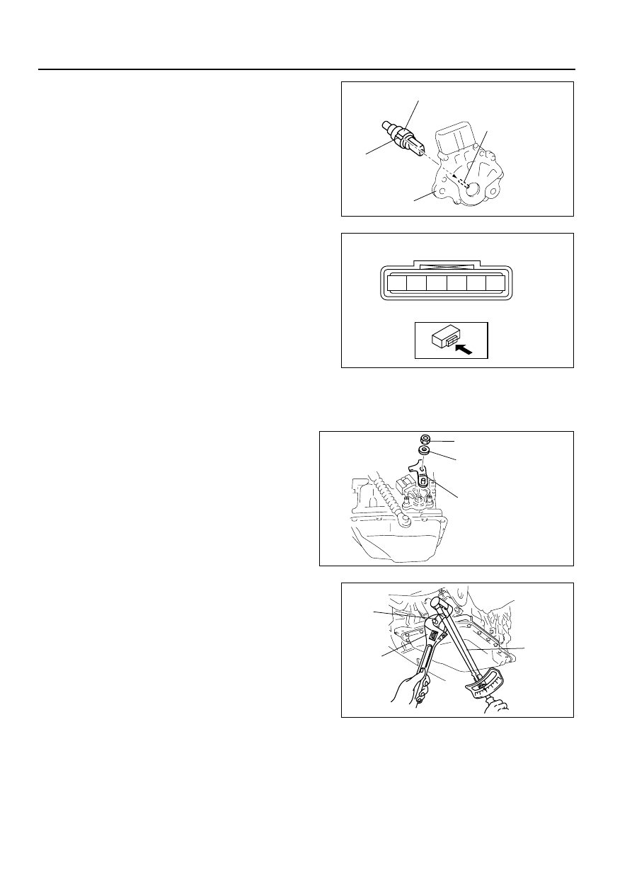
(3) Install the TR switch while aligning the protrusion
and groove as shown.
(4) hand- tighten the TR switch mounting bolts.
(5) Inspect the resistance between the terminals B
and C.
• If not as specified, readjust the TR switch.
Resistance
750 ohms
(6) Tighten the TR switch mounting bolts
Tightening torque
8—11 N·m
{82—112 kgf·cm, 71—97 in·lbf}
Caution
• Do not use an impact wrench. Hold the manual shaft lever when removing the manual shaft nut, or
the transaxle may be damaged.
(7) Install the manual shaft lever and the washer.
(8) Set the adjustable wrench as shown to hold
the manual shaft lever, and tighten the manual
shaft nut.
Tightening torque
32—46 N·m
{3.2—4.7 kgf·m, 24—33 ft·lbf}
63. Install the transaxle range switch. (9-terminal
connector type)
TR SWITCH
GROOVE
MANUAL SHAFT
PROTRUSION
B3E0517A317
F
E
D
C
B
A
TR SWITCH
B3E0517A316
MANUAL SHAFT
LEVER
WASHER
MANUAL SHAFT NUT
B3E0517A318
MANUAL
SHAFT
LEVER
ADJUSTABLE
WRENCH
TORQUE
WRENCH
B3E0517A319