Mazda 5. Manual - part 44


  Index      Mazda     Mazda 5 - service repair manual


Search            


Content   ..  42  43  44  45   ..


Mazda 5. Manual - part 44


05–17–96

AUTOMATIC TRANSAXLE 

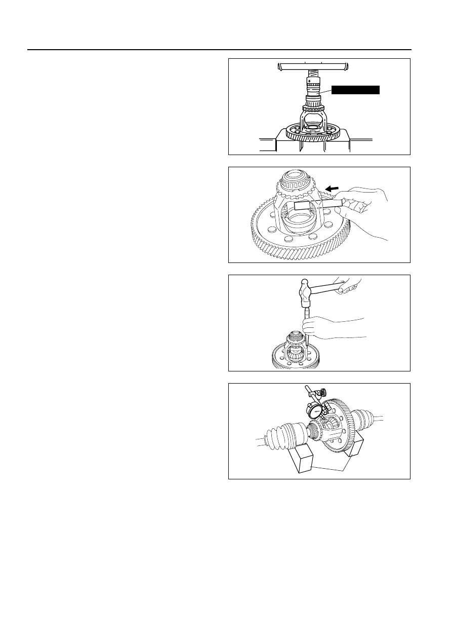
(2) Press on the other new bearing (ring gear 

side) in the same manner.

5. Apply ATF to the thrust washers and pinion shaft.
6. Install the pinion gear and thrust washers into the 

gear case.

7. Install the pinion shaft.

8. Install the roll pin, and crimp it to prevent it from 

coming out of the gear case.

9. Apply ATF to the thrust washers.

10. Install the thrust washers and side gears into the 

gear case, then turn the side gears and align 
them with the drive shaft holes.

11. Measure the backlash of the side gears as 

follows:
(1) Install the left and right drive shafts in the 

differential.

(2) Support the drive shafts on V-blocks.

(3) Measure the backlash of both side gears.

Backlash

Standard: 0.05—0.15 mm {0.002—0.005 in}
Maximum: 0.5 mm {0.020 in}

• If not as specified, replace the differential.

End Of Sie

SECONDARY GEAR BEARING PRELOAD

B3E051719204A03

1. Set the primary gear into the transaxle case.

(See 05–17–102 AUTOMATIC TRANSAXLE ASSEMBLY.)

49 G030 338

B3E0517A275

B3E0517A276

B3E0517A277

V-BLOCKS

B3E0517A278

AUTOMATIC TRANSAXLE 

05–17–97

05

2. Remove the bearing race and adjustment shim 

from the converter housing using the SST.

3. Install the funnel and bearing race into the 

transaxle case.

4. Set the secondary gear and output gear into the 

transaxle case.

5. Install the bearing race removed in Step 2 into the 

secondary gear and output gear.

6. Set the SSTs onto the primary gear and 

secondary gear and output gear.

7. Turn the selector to eliminate the gap between its 

two halves.

49 W032 2A0

B3E0517A174

FUNNEL

BEARING RACE

B3E0517A175

BEARING RACE

SECONDARY GEAR 
AND OUTPUT GEAR

B3E0517A176

49 B019 017

49 B019 019

B3E0517A177

49 B019 017

A

B

B3E0517A178

05–17–98

AUTOMATIC TRANSAXLE 

8. Set the six SSTs (collars) on the transaxle case in 

the position shown.

9. Set the converter housing on the transaxle case 

and tighten the SSTs (bolts) to the specified 
torque.

Tightening torque

19—25 N·m {1.9—2.6 kgf·m, 14—18 ft·lbf}

10. Turn the SST (selector) to increase the clearance 

(arrow) using the SSTs (bars), until it no longer 
turns. This is to seat the bearing race.

11. Turn the selector in the opposite direction until the 

preload is eliminated (gap is reduced).

12. Insert the joint through the converter housing and 

attach it the SST installed to the primary gear.

Note

• Read the preload when the primary gear 

starts to turn.

• Measure several times and calculate the 

average value.

13. Adjust the clearance of the SST (selector) to 

obtain the specified preload reading.

Preload:

1.5—2.4 N·m {15—25 kgf·cm, 13—22 in·lbf}

*1

0.4—1.5 N·m {5—15 kgf·cm, 4—13 in·lbf}

*2

*1 : Applied VIN (assumed): JM0 DY10Y100 

100001—106898 JM6 DY10Y100 100001—
106898

*2 : Except *1

Note

• Measure the clearance around the entire 

circumference, and select a shim based on the maximum clearance.

• The maximum allowable number of adjustment shim is one.

14. Measure the clearance as shown.

49 FT01 384

49 FT01 384

B3E0517A179

49 B019 018

49 B019 018

B3E0517A180

49 F401 385

B3E0517A181

TORQUE WRENCH

B3E0517A182

AUTOMATIC TRANSAXLE 

05–17–99

05

15. Take the maximum reading and determine the 

shim to be used.

Adjustment shim sizes

mm {in}

*1 : Applied VIN (assumed): JM0 DY10Y100 

100001—106898 JM6 DY10Y100 100001—
106898

*2 : Except *1

16. Remove the converter housing and SST (selector).
17. Install the required adjustment shim and tap the 

bearing race into the converter housing.

18. Install the converter housing.

Tightening torque

19—25 N·m {1.9—2.6 kgf·m, 14—18 ft·lbf}

19. Insert the SST (preload adapter) through the 

converter housing and attach it to the SST.

20. Verify that the preload is within the specification. If 

not, return to Step 1.

Preload:

1.5—2.4 N·m {15—25 kgf·cm, 13—22 in·lbf}

*1

0.4—1.5 N·m {5—15 kgf·cm, 4—13 in·lbf}

*2

*1 : Applied VIN (assumed): JM0 DY10Y100 100001—106898 JM6 DY10Y100 100001—106898
*2 : Except *1

21. Remove the converter housing.

End Of Sie

DIFFERENTIAL BEARING PRELOAD

B3E051719204A04

1. Remove the bearing race and adjustment shim 

from the converter housing using the SST.

0.45 {0.018}

*2

0.50 {0.020}

0.55 {0.022}

0.60 {0.024}

0.65 {0.026}

0.70 {0.028}

0.75 {0.030}

0.80 {0.031}

0.85 {0.033}

0.90 {0.035}

0.95 {0.037}

1.00 {0.039}

1.05 {0.041}

1.10 {0.043}

1.15 {0.045}

1.20 {0.047}

1.25 {0.049}

1.30 {0.051}

*1

B3E0517A184

B3E0517A185

49 W032 2A0

B3E0517A186


Content   ..  42  43  44  45   ..