Mazda 5. Manual - part 43


  Index      Mazda     Mazda 5 - service repair manual


Search            


Content   ..  41  42  43  44   ..


Mazda 5. Manual - part 43


05–17–92

AUTOMATIC TRANSAXLE 

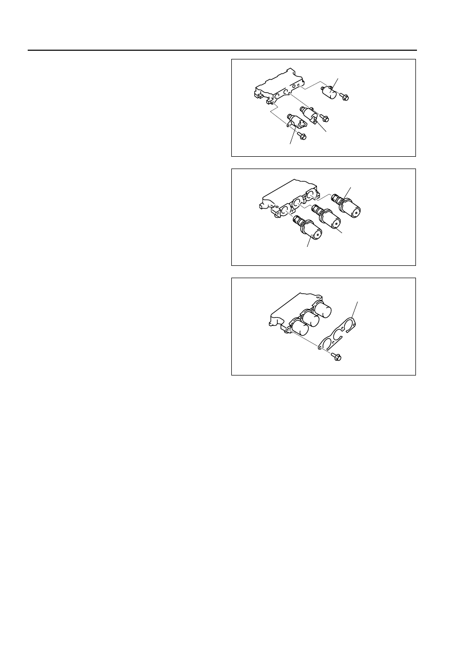
10. Install the shift solenoid D, E, and pressure 

control solenoid.

Tightening torque

7.8—10.8 N·m

{80—110 kgf·cm, 69—95.5 in·lbf}

11. Install the shift solenoid A, B, C.

12. Install the bracket.

Tightening torque

7.8—10.8 N·m

{80—110 kgf·cm, 69—95.5 in·lbf}

13. Install the packing.
14. Apply ATF to new O-ring and install it onto the oil 

strainer.

15. Install the oil strainer onto the main control valve 

body.

End Of Sie

DIFFERENTIAL DISASSEMBLY/ASSEMBLY

B3E051727100A01

1. Perform the preinspeciton before disassembly. (See 05–17–129 Differential Preinspection.)
2. Disassemble in the order indicated in the table.
3. Assemble in the reverse order of disassembly.

SHIFT SOLENOID VALVE D

PRESSURE CONTROL 
SOLENOID

SHIFT SOLENOID VALVE E

B3E0517A151

SHIFT SOLENOID B

SHIFT SOLENOID C

SHIFT SOLENOID A

B3E0517A150

BRACKET

B3E0517A149

AUTOMATIC TRANSAXLE 

05–17–93

05

RIVET FIXED TYPE

.

BOLT FIXED TYPE

.

8

7

9

7

5

4

3

SST

SST

SST

R

R

R

6

6

ATF

ATF

ATF

ATF

ATF

ATF

ATF

ATF

1

1

2

2

B3E0517A266

1

Side gear 

2

Thrust washer 

3

Roll pin
(See 05–17–94 Roll Pin Disassembly Note.)

4

Pinion shaft

5

Pinion gear 

6

Thrust washer 

7

Bearings
(See 05–17–94 Bearings Disassembly Note.)

8

Sensor rotor
(See 05–17–95 Sensor Rotor Disassembly Note.)

9

Ring gear and gear case 

10

11

8

7

9

7

5

4

3

SST

SST

SST

R

R

R

6

6

ATF

ATF

ATF

ATF

ATF

ATF

ATF

ATF

1

1

2

2

152—176.4 N·m 
{15.5—17.9 kgf·m, 
112—130 ft·lbf}

B3E0517A267

05–17–94

AUTOMATIC TRANSAXLE 

Roll Pin Disassembly Note

1. Place the gear case in a vise.
2. Insert a 2.0 mm {0.07 in} punch into the roll pin 

hole from the ring gear side, and remove the roll 
pin.

Bearings Disassembly Note

1. Remove the bearing (speedometer drive gear 

side) from the gear case using the SSTs.

2. Remove the bearing (ring gear side) from the 

gear case using the SST.

1

Side gear 

2

Thrust washer 

3

Roll pin
(See 05–17–94 Roll Pin Disassembly Note.)

4

Pinion shaft

5

Pinion gear 

6

Thrust washer 

7

Bearings
(See 05–17–94 Bearings Disassembly Note.)

8

Sensor rotor
(See 05–17–95 Sensor Rotor Disassembly Note.)

9

Ring gear

10

Gear case

11

Bolt

B3E0517A268

49 F401 366A

49 G030 160

49 B017 209

B3E0517A269

49 0839 425C

B3E0517A270

AUTOMATIC TRANSAXLE 

05–17–95

05

Sensor Rotor Disassembly Note

• Remove the sensor rotor from the gear case 

using the SSTs.

Assembly Procedure

1. Install the ring gear to the gear case. (bolt fixed 

type)

2. Tighten the bolts evenly and gradually in the order 

shown. (bolt fixed type)

Tightening torque

152—176 N·m 

{15.5—17.9 kgf·m, 112—130 ft·lbf}

3. Install the sensor rotor to the gear case using the 

SST and suitable plate.

4. Install a new bearing.

(1) Press the new bearing (speedometer drive 

gear side) onto the gear case using the SST.

49 0839 425C

49 B019 014

B3E0517A271

B3E0517A272

9

8

7

5

4

3

10

14

13

11

12

6

1

2

B3E0517A273

49 S231 626

SUITABLE PLATE

SENSOR ROTOR

B3E0517A274


Content   ..  41  42  43  44   ..