Mazda 5. Manual - part 25


  Index      Mazda     Mazda 5 - service repair manual


Search            


Content   ..  23  24  25  26   ..


Mazda 5. Manual - part 25


05–17–20

AUTOMATIC TRANSAXLE 

lubrication passage of the turbine shaft.

.

End Of Sie

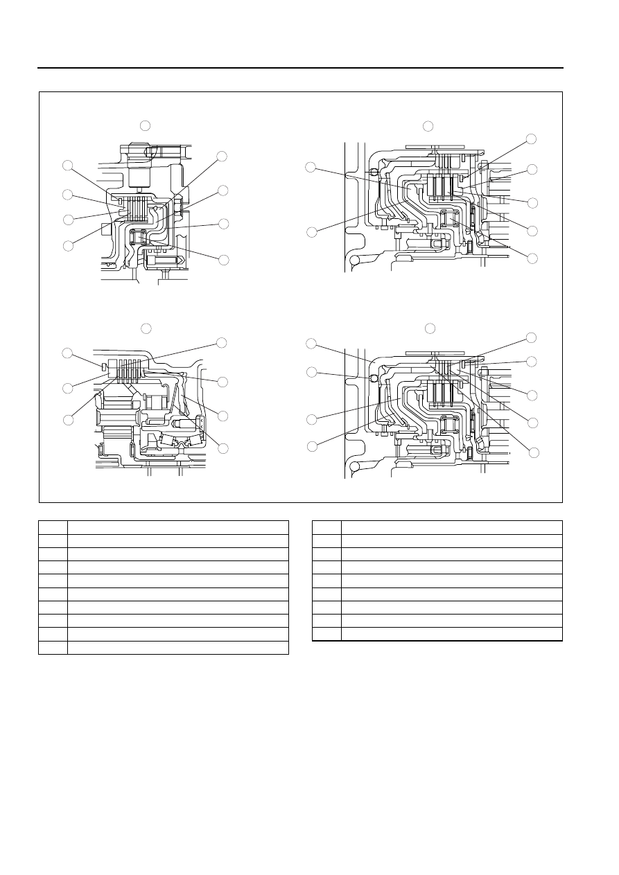
CENTRIFUGAL BALANCE CLUTCH OUTLINE

B3E051701030A11

• The centrifugal balance clutch mechanism, which cancels the centrifugal oil pressure, is adopted for improve 

clutch control.

• A bonded seal piston (press-worked component of a piston and a seal) is adopted for each clutch and brake to 

reduce the piston size and weight.

End Of Sie

CENTRIFUGAL BALANCE CLUTCH STRUCTURE

B3E051701030A12

• Centrifugal balance clutch chambers are installed opposite the clutch chamber. The centrifugal balance clutch 

chambers are constantly filled with ATF from an exclusive hydraulic passage of the turbine shaft.

End Of Sie

3

1

2

4

5

5

5

5

6

6

6

6

7

7

7

7

8

8

12

11

10

9

9

13

12

14

8

8

14

17

19

18

16

15

16

B3E0517A002

1

Forward clutch

2

3-4 clutch

3

Low and reverse brake

4

Reverse clutch

5

Snap ring

6

Retaining plate

7

Drive plate

8

Driven plate

9

Centrifugal balance chamber

10

Seal plate

11

Forward clutch piston (bonded seal piston)

12

Spring and retainer component

13

3-4 clutch piston (bonded seal piston)

14

Dish plate

15

Low and reverse brake piston (bonded seal piston)

16

Piston return spring

17

2-4 brake drum

18

Piston check ball

19

Reverse clutch piston (bonded seal piston)

AUTOMATIC TRANSAXLE 

05–17–21

05

CENTRIFUGAL BALANCE CLUTCH OPERATION

B3E051701030A13

When clutch pressure is not applied

• When the clutch drum rotates, centrifugal force acts on the residual ATF in the clutch chamber to push against 

the piston. However, centrifugal force also acts on the ATF filling the centrifugal balance clutch chamber to push 
back the piston. As a result, the two forces are eliminated and the piston remains stationary, thus preventing 
clutch engagement.

When clutch pressure is applied

• When clutch pressure is applied to the clutch chamber, the clutch pressure overcomes the oil pressure and 

spring force in the opposite centrifugal balance clutch chamber, and pushes the piston to engage the clutches. 
Because the centrifugal force acting on the clutch pressure in the clutch chamber is canceled by another 
centrifugal force acting on the ATF filling the centrifugal balance clutch chamber, the influence of the centrifugal 
force created by the clutch drum revolution speed is eliminated. As a result, stable piston pushing force is 
obtained in all rotation ranges, and smoother shifts can be made.

.

End Of Sie

2-4 BRAKE BAND OUTLINE

B3E051701030A14

• The 2-4 brake band locks the 2-4 brake drum and fixes the rear sun gear. The 2-4 brake band operates in 2GR 

or 4GR.

End Of Sie

2-4 BRAKE BAND STRUCTURE

B3E051701030A15

• The 2-4 brake band is set to wind the 2-4 brake drum and one end of the 2-4 brake band is fixed with a band 

strut. The servo piston is in the transaxle case.

End Of Sie

2-4 BRAKE BAND OPERATION

B3E051701030A16

• When the hydraulic pressure acts between the servo retainer and the servo piston (2-4 brake band 

engagement side), the servo piston acts on the 2-4 brake band to lock the 2-4 brake drum. At the same time, 
the servo return spring also works as resistance to obtain the optimal 2-4 brake band engagement force.
When the hydraulic pressure acts between the servo piston and the transaxle case (2-4 brake band release 
side), the servo piston is pushed to the servo retainer side. This causes the 2-4 brake band to extend by its own 
spring force and unlock the 2-4 brake drum.

7

5

5

8

4

3

6

6

17

18

13

12

14

16

15

10

11

19

9

1

2

6

15

B3E0517T012

1

Structure

2

Operation

3

Clutch drum

4

Clutch

5

Seal

6

Clutch pressure

7

Clutch chamber

8

Bonded seal piston

9

Balance chamber

10

Seal plate

11

Lubrication passage

12

Centrifugal hydraulic pressure of piston chamber

13

Spring force

14

Centrifugal hydraulic pressure of balance chamber

15

Changes according to the rotation speed of clutch 
drum

16

Two forces are eliminated

17

Drum revolution speed

18

Piston pushing force

19

Piston pushing force required to obtain shift quality

05–17–22

AUTOMATIC TRANSAXLE 

When the hydraulic pressure acts between the servo retainer and the servo piston and between the servo 
piston and the transaxle case simultaneously, the servo piston is pushed to the servo retainer side and the 2-4 
brake drum is unlocked because of the difference in the two areas and spring force.

.

End Of Sie

ONE-WAY CLUTCH OUTLINE

B3E051701030A17

• The one-way clutch locks the counterclockwise rotation (seen from the torque converter side) of the front 

internal gear. The one-way clutch operates in D, M, S, and L range of the first gear.

End Of Sie

ONE-WAY CLUTCH STRUCTURE

B3E051701030A18

• The one-way clutch outer race is integrated with the front internal gear, and the one-way clutch inner race is 

fixed to the transaxle case.

End Of Sie

ONE-WAY CLUTCH OPERATION

B3E051701030A19

• The one-way clutch outer race (front internal gear) rotates clockwise (seen from the torque converter side) 

freely, but the sprags rise to lock the rotation when the outer race tries to rotate counterclockwise.

• The one-way clutch locks the counterclockwise rotation of the front internal gear, and also locks the 

counterclockwise revolution of the rear planetary gear via the rear planetary carrier.

Note

• All direction of rotation are viewed from the torque converter.

7

5

4

3

6

1

2

B3E0517A003

1

Band strut

2

Servo return spring

3

Release side

4

Servo  retainer

5

Engagement side

6

Servo piston

7

2-4 brake band

AUTOMATIC TRANSAXLE 

05–17–23

05

.

End Of Sie

PLANETARY GEAR OUTLINE

B3E051701030A20

• The planetary gear is a transaxle which converts the driving force of the turbine shaft to the optimal driving 

force and transmits it to the output gear through the operation of each clutch and brake.

• A double arranged gear with a single planetary gear unit is adopted for the planetary gear; they are the front 

planetary gear and the rear planetary gear (from converter side).

• The planetary gear consists of the internal gear, planetary carrier (pinion gears), and the sun gear.

3

1

2

3

5

4

6

7

B3E0517A004

1

One-way clutch outer race (front internal gear) 
cannot rotate

2

One-way clutch outer race (front internal gear) can 
rotate

3

One-way clutch inner race (fixed to transaxle case)

4

One-way clutch outer race (front internal gear)

5

One-way clutch

6

One-way clutch inner race

7

Transaxle case


Content   ..  23  24  25  26   ..