Mazda 5. Manual - part 14


  Index      Mazda     Mazda 5 - service repair manual


Search            


Content   ..  12  13  14  15   ..


Mazda 5. Manual - part 14


01–10–42

MECHANICAL 

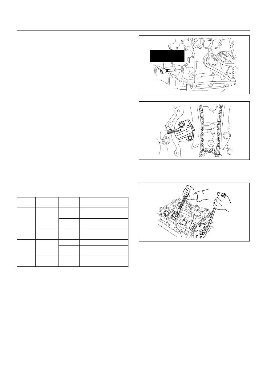
3. Install the SST as shown in the figure.
4. Turn the crankshaft clockwise so that the 

crankshaft is in the No.1 cylinder TDC position.

5. Install the timing chain.

6. Install the chain tensioner and remove the 

retaining wire.

Camshaft Sprocket, Variable Valve Timing Actuator (With variable valve timing mechanism) Assembly Note

1. Hold the camshaft using a suitable wrench on the cast hexagon as shown in the figure.
2. Tighten the camshaft sprocket lock bolt.

N·m {kgf·m, ft·lbf}

TYPE A : Bolt (Gold), Washer (Gold)
TYPE B : Washer based bolt (Black)
TYPE C : Bolt (Black), Washer (Gray)
*

1

: With variable valve timing mechanism

Front Oil Seal Assembly Note

1. Apply clean engine oil to the oil seal.
2. Push the oil seal slightly in by hand.

303-507

(49 JE01 061)

B3E0110E110

B3E0110E126

Engine 

type

Camshaft 

sprocket

Bolt type

Tightening torque 

L8
LF
L3

IN side

B

89—95 

{9.1—9.6, 65.7—70.0}

C

69—75 

{7.1—7.6, 50.9—55.3}

EX side

A, C

69—75 

{7.1—7.6, 50.9—55.3}

L3*

1

LF*

1

IN side

A

Can not use

B, C

69—75 

{7.1—7.6, 50.9—55.3}

EX side

A, C

69—75 

{7.1—7.6, 50.9—55.3}

B3E0110E095

MECHANICAL 

01–10–43

01

3. Compress the oil seal using the SST and a 

hammer.

Engine Front Cover Assembly Note

1. Apply silicone sealant to the engine front cover as shown in the figure.

Caution

• Install the cylinder head cover within 10 min of applying the silicone sealant.

• Silicone sealant is not need in area C as indicated below due to an existing. (With variable valve 

timing mechanism)

Thickness

 A: 2.0—3.0 mm {0.079—0.118 in}
 B: 1.5—2.5 mm {0.059—0.098 in}

49 H010 401

B3E0110E127

HAMMER

FRONT OIL SEAL

OIL PUMP BODY

49 B014 001

0—0.5 mm 
{0—0.019 in}

B3E0110E134

A

B

B

C

B3E0110E129

01–10–44

MECHANICAL 

2. Install the cylinder head cover bolts in the order 

as shown in the figure.

Crankshaft Pulley Lock Bolt Assembly Note

1. Install the SST to the camshaft as shown in the figure.

Europe

Except Europe

Bolt No.

Tightening torque N·m {kgf·m, ft·lbf}

1—18

8.0—11.5 N·m
{81.6—117.2 kgf·cm, 70.9—101.7 in·lbf}

19—22

40—55 {4.1—5.6, 29.7—40.5}

9

8

7

5

4

3

1

2

10

6

19

18

17

15

16

14

13

11

12

20

21

22

B3E0110E062

49 JE01 054

B3E0110E099

303-376

(49 UN30 3376)

B3E0110E100

MECHANICAL 

01–10–45

01

2. Install the M6 

× 1.0 bolt in by hand.

3. Turn the crankshaft clockwise so that the 

crankshaft is in the No.1 cylinder TDC position.

4. Hold the crankshaft pulley using the SST.
5. Tighten the crankshaft pulley lock bolt in the order 

shown following two steps using the SST (49 
D032 316)
.

Tightening torque

(1) 96—104 N·m

{9.8—10.6 kgf·m, 70.9—76.7 ft·lbf}

(2) 87

°—93°

6. Remove the M6 

× 1.0 bolt.

7. Remove the SST from the camshaft.
8. Remove the SST from the block lower blind plug.
9. Rotate the crankshaft clockwise two turns until 

the TDC position.

• If not aligned, loosen the crankshaft pulley lock bolt and repeat from Step 1.

10. Install the cylinder block lower blind plug.

Tightening torque 
20 N·m {2.0 kgf·m, 14.8 ft·lbf}

Cylinder Head Cover Assembly Note

1. Apply silicone sealant to the mating faces as shown in the figure.

Caution

• Install the cylinder head cover within 10 min of applying the silicone sealant.

Dot diameter 
4.0—6.0 mm {0.16—0.23 in}

2. Install the cylinder head cover with a new gasket.

BOLT

B3E0110E063

49 B011 105

205-072

(49 UN20 5072)

B3E0110W107

SEALANT

SEALANT

B3E0110E064


Content   ..  12  13  14  15   ..