Mazda 5. Manual - part 12


  Index      Mazda     Mazda 5 - service repair manual


Search            


Content   ..  10  11  12  13   ..


Mazda 5. Manual - part 12


01–10–34

MECHANICAL 

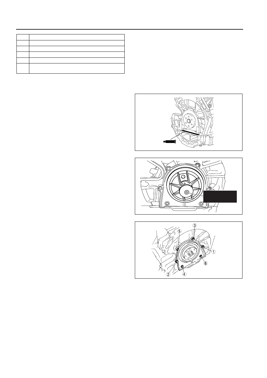
Rear Oil Seal Assembly Note

1. Apply silicone sealant to the mating faces as shown in the figure.

Thickness
 4.0—6.0 mm {0.16—0.23 in}

2. Apply clean engine oil to the new oil seal lip.

3. IInstall the rear oil seal using the SST as shown in 

the figure.

4. Tighten the rear oil seal bolts in the order as 

shown in the figure. (Except TRIBUTE (L.H.D.) 
Face-lifted model.)

Tightening torque
8.0—11.5 N·m
{81.6—117.2 kgf·cm, 70.9—101.7 in·lbf}

Drive Plate (ATX), Flywheel (MTX) Assembly Note

1. Hold the crankshaft using the SST.

9

Knock sensor

10

Oil cooler

11

Oil filter adapter

12

Oil filter

13

Oil filter cover (cartridge type)

14

Oil pan
(See 01–10–35 Oil pan Assembly Note)

SEALANT

B3E0110E114

303-328

(49 UN30 3328)

CUE110BW2005

AME2224E002

MECHANICAL 

01–10–35

01

2. Tighten the bolts in the 3 steps in the figure.

Tightening torque
(1) 46—54 N·m 
{4.70—5.50 kgf·m, 34.0—39.8 ft·lbf
(2) 76—84 N·m 
{7.75—8.56 kgf·m, 56.1—61.9 ft·lbf
(3) 108—116 N·m 
{11.1—11.8 kgf·m, 79.7—85.5 ft·lbf

Oil pan Assembly Note

1. Apply a continuous bead of silicone sealant to the 

oil pan as indicated in the figure.

2.  Use a square ruler to unite the oil pan and the 

cylinder block junction side on the engine front 
cover side.

3. Tighten the rear oil pan bolts in the order as 

shown in the figure.

Tightening torque

20—30 N·m 
{2.1—3.0 kgf·m, 15.2—21.6 in·lbf}

End Of Sie

AME2224E102

ENGINE FRONT SIDE

2.5 mm{0.099 in}

REAR OIL SEAL

B3E0110E121

-0.05—0.05 mm {-0.0020—0.0020 in}

CYLINDER 
BLOCK

OIL PAN

B3E0110E120

9

8

7

5

4

3

1

2

10

6

13

11

12

B3E0110E122

01–10–36

MECHANICAL 

CYLINDER HEAD (I) ASSEMBLY

B3E011002000222

1. Assemble in the order indicated in the table.

.

Valve Seal Assembly Note

1. Press the valve seal onto the valve guide by hand.
2. Lightly tap the SST using a plastic hammer.

Valve Keeper Assembly Note

1. Install the valve keeper using the SSTs.

8

8

7

5

4

3

1

2

6

SST

SST

R

R

42—48 {4.3—4.8, 
31.0—35.4}

42—48 {4.3—4.8, 31.0—35.4}

56—60 {5.8—6.1, 
41.3—44.2}

8.0—11.5 N·m {81.6—117.2 
kgf·cm, 70.9—101.7 in·lbf}

N·m { kgf·m, ft·lbf}

B3E0110E130

1

Water outlet case

2

EGR pipe

3

Valve seal
(See 01–10–36 Valve Seal Assembly Note)

4

Valve

5

Valve spring

6

Upper valve spring seat

7

Valve keeper
(See 01–10–36 Valve Keeper Assembly Note)

8

Engine hanger

VALVE 
SEAL

49 T032  302

B3E0110E123

MECHANICAL 

01–10–37

01

When using the SSTs (49 0636 100B, 49 B012 0A2)

When using the SST (49 JE02 0A2) (Europe only)

End Of Sie

CYLINDER HEAD (II) ASSEMBLY

B3E011002000211

1. Assemble in the order indicated in the table.

49 B012 0A2

49 0636 100B

B3E0110E124

49 JE02 0A2

CUE110ZER01


Content   ..  10  11  12  13   ..