Mazda 5. Manual - part 9


  Index      Mazda     Mazda 5 - service repair manual


Search            


Content   ..  7  8  9  10   ..


Mazda 5. Manual - part 9


01–10–22

MECHANICAL 

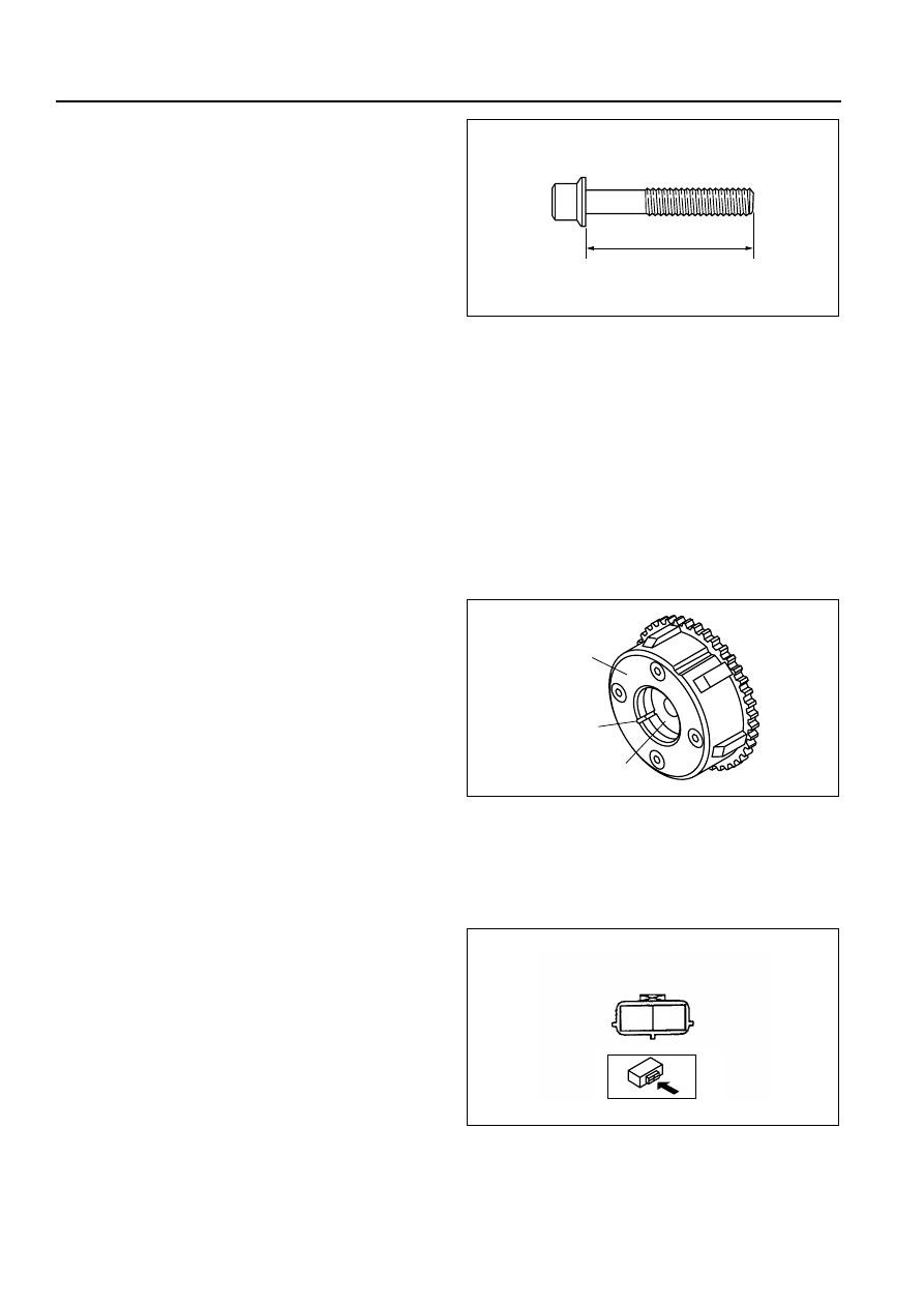
Bolt length (mm {in})

Cylinder head bolt (With washer)
 Standard: 149.2—145.8 {5.87—5.90}
 Maximum: 150.5 {5.91}
Cylinder head bolt (Without washer)
 Standard: 145.2—145.8 {5.72—5.74}
 Maximum: 146.5 {5.77}
Connecting rod bolt
 Standard: 44.7—45.3 {1.75—1.78}
 Maximum: 46.0 {1.81}
Main bearing cap bolt (Plastic region 

tightening bolt only)

 Standard: 110.0—110.6 {4.33—4.35}
 Maximum: 113.3{4.38}

End Of Sie

VARIABLE VALVE TIMING ACTUATOR INSPECTION

B3E011000142201

Caution

• Variable valve timing actuator cannot be disassembled because it is a precision unit.

1. Confirm that the groove of the rotor and notch of the cover at the variable valve timing actuator are aligned and 

fixed.

• If the notch and the bump are not aligned, rotate the rotor toward the valve timing retard position by hand 

until they are in place.

• If the rotor and cover are not fixed even though their notch and groove are aligned, replace the variable 

valve timing actuator.

End Of Sie

OIL CONTROL VALVE (OCV) INSPECTION

B3E011014420201

Coil resistance inspection

1. Disconnect the negative battery cable.
2. Disconnect the oil control valve (OCV) connector.
3. Measure the resistance between terminals A and B using an ohmmeter.

• If not as specified, replace the oil control valve (OCV).

Specification

6.9—7.9 ohms [20 

°C {68 °F}]

4. Connect the oil control valve (OCV) connector.

Spool valve operation inspection

1. Disconnect the negative battery cable.
2. Remove the oil control valve (OCV).
3. Verify that the spool valve in the oil control valve (OCV) is in the maximum valve timing retard position as 

L

B3E0110E088

COVER

NOTCH

ROTOR

B3E0110E089

A

B

OIL CONTROL VALVE (OCV)

B3E2226W002

MECHANICAL 

01–10–23

01

indicated in the figure.

• If it exceeds the specification, replace the oil control valve (OCV).

4. Verify that the battery is fully charged.

• If it is less than specification, recharge the 

battery.

5. Apply battery positive voltage between the oil 

control valve (OCV) terminals and verify that the 
spool valve operates and moves to the maximum 
valve timing advance position.

• If it exceeds the specification, replace the oil 

control valve (OCV).

Note

• When applying battery positive voltage 

between the oil control valve (OCV) 
terminals, the connection can be either of 
the following:

— Positive battery cable to terminal A, negative battery cable to terminal B

— Positive battery cable to terminal B, negative battery cable to terminal A

6. Stop applying battery positive voltage and verify 

that the spool valve returns to the maximum valve 
timing retard position.

• If it exceed the specification, replace the oil 

control valve (OCV).

End Of Sie

VALVE CLEARANCE INSPECTION

B3E011012111203

1. Measure the valve clearance as follows.

(1) Turn the crankshaft clockwise so that the No.1 piston is at TDC of the compression stroke.
(2) Measure the valve clearance at A in the figure.

• If the valve clearance exceeds the standard, replace the tappet. (See 01–10–24 VALVE CLEARANCE 

ADJUSTMENT.)

Note

• Make sure to note the measured values for choosing the suitable replacement tappets.

Standard [Engine cold]

IN: 0.22—0.28 mm {0.0087—0.0110 in}
EX: 0.27—0.33 mm {0.0106—0.0130 in}

(3) Turn the crankshaft 360

° clockwise so that the 

No.4 piston is at TDC of the compression 
stroke.

(4) Measure the valve clearance at B in the 

figure.

• If the valve clearance exceeds the 

standard, replace the tappet. (See 01–
10–24 VALVE CLEARANCE 
ADJUSTMENT.)

Note

• Make sure to note the measured values for choosing the suitable replacement tappets.

Standard [Engine cold]

IN: 0.22—0.28 mm {0.0087—0.0110 in}
EX: 0.27—0.33 mm {0.0106—0.0130 in}

SPOOL VALVE
(MAXIMUM VALVE TIMING RETARD POSITION

B3E0110E090

VALVE TIMING 
ADVANCE

VALVE TIMING 
RETARD

SPOOL VALVE
(MAXIMUM VALVE TIMING ADVANCE POSITION)

B3E0110E091

A

A

A

A

B

B

B

B

EX

IN

B3E0110E092

01–10–24

MECHANICAL 

End Of Sie

VALVE CLEARANCE ADJUSTMENT

B3E011012111204

1. Remove the engine front cover lower blind plug.
2. Remove the engine front cover upper blind plug.
3. Remove the cylinder block lower blind plug.

4. Install the SST as shown in the figure.
5. Turn the crankshaft clockwise so that the 

crankshaft is in the No.1 cylinder TDC position.

6. Loosen the timing chain.

(1) Using a suitable screwdriver or equivalent 

tool, unlock the chain tensioner ratchet.

(2) Turn the exhaust camshaft clockwise using a 

suitable wrench on the cast hexagon and 
loosen the timing chain.

(3) Placing the suitable bolt (M6 

× 1.0 Length 

25—35 mm {0.9—1.3 in}) at the engine front 
cover upper blind plug hole, secure the chain 
guide at the position where the tension is 
released.

UPPER 
BLIND 
PLUG

LOWER BLIND 
PLUG

B3E0110E093

303-507

(49 JE01 061)

B3E0110E094

3

1

2

BOLT (M6 x 1.0)

B3E0110E096

MECHANICAL 

01–10–25

01

7. Hold the exhaust camshaft using a suitable 

wrench on the cast hexagon as shown in the 
figure.

8. Remove the exhaust camshaft sprocket.

9. Loosen the camshaft cap bolts in several passes 

in the order shown in the figure.

Note

• The cylinder head and the camshaft caps 

are numbered to make sure they are 
reassembled in their original position. When 
removed, keep the caps with the cylinder 
head they were removed from. Do not mix 
the caps.

10. Remove the camshaft.
11. Remove the tappet.
12. Select proper adjustment shim.

New adjustment shim

= Removed shim thickness + Measured valve clearance - Standard valve clearance (IN: 0.25 mm 

{0.0098 in}, EX: 0.30 mm {0.0118 in})

Standard [Engine cold]

IN: 0.22—0.28 mm {0.0087—0.0110 in}
EX: 0.27—0.33 mm {0.0106—0.0130 in}

13. Install the camshaft with No.1 cylinder aligned with the TDC position.
14. Tighten the camshaft cap bolt using the following 

two steps.

Tightening torque

(1) 5.0—9.0 N·m 

{51.0—91.7 kgf·cm, 44.3—79.5 in·lbf}

(2)14.0—17.0 N·m 

{1.43—1.73 kgf·m, 10.4—12.5 ft·lbf}

B3E0110E095

EXHAUST 
CAMSHAFT 
SPROCKET

B3E0110E097

9

8

7

5

4

3

1

2

10

19

18

17

15

16

14

13

11

12

20

6

B3E0110E057

9

8

7

5

4

3

1

2

10

19

18

17

15

16

14

13

11

12

20

6

B3E0110E098


Content   ..  7  8  9  10   ..