Mazda X-5. Manual - part 122
CONTROL SYSTEM
09–40–1
09–40
09–40
CONTROL SYSTEM
CONTROLLER AREA NETWORK (CAN)
SYSTEM OUTLINE . . . . . . . . . . . . . . . . 09–40–1
CAN SYSTEM STRUCTURAL VIEW . . . 09–40–1
CAN SYSTEM WIRING DIAGRAM . . . . . 09–40–1
CAN SYSTEM DESCRIPTION . . . . . . . . 09–40–2
Mechanism of CAN System-Related
Module . . . . . . . . . . . . . . . . . . . . . . . . 09–40–2
Twisted Pair . . . . . . . . . . . . . . . . . . . . . . 09–40–2
Time Division Multiplex . . . . . . . . . . . . . 09–40–3
Vehicle CAN System . . . . . . . . . . . . . . . 09–40–3
CAN Signal-Chart . . . . . . . . . . . . . . . . . 09–40–4
On-Board Diagnostic Function . . . . . . . 09–40–5
End of Toc
CONTROLLER AREA NETWORK (CAN) SYSTEM OUTLINE
E5U094055430N01
• Due to the simplification of the wiring harness, a CAN system for transmission of multiplex input/output signals
among electrical modules has been adopted.
• Twisted-pair wiring is used for connections between the following modules. (Each electrical module hereafter
referred to as a CAN system-related module):
— PCM
— TCM
— DSC HU/CM (with DSC)
— ABS HU/CM (with ABS)
— Keyless control module (with advanced keyless system)
— Steering angle sensor (with DSC)
— Instrument cluster
• With an on-board diagnostic function included for each multiplex module, display of DTCs using the WDS or
equivalent has improved serviceability.
End Of Sie
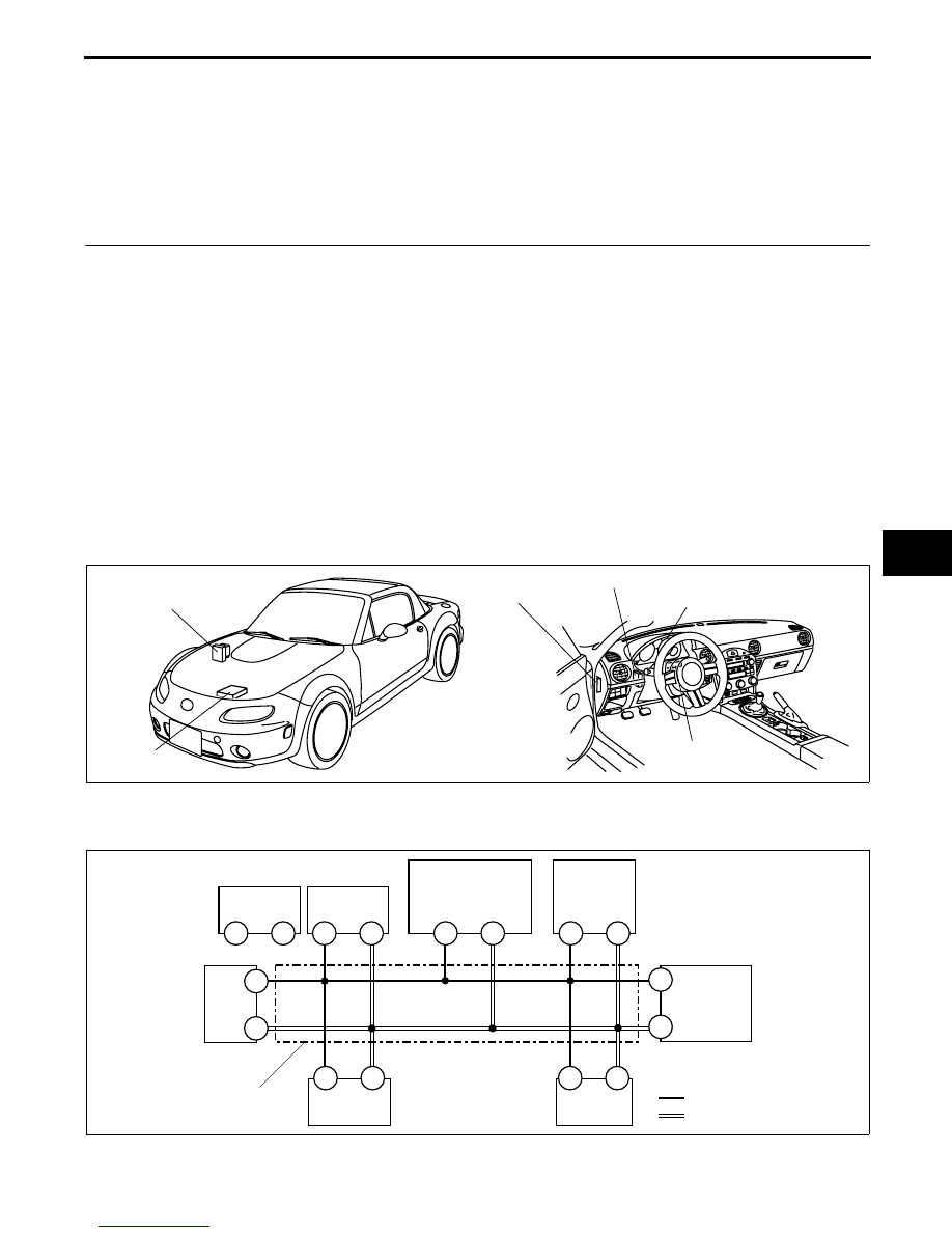
CAN SYSTEM STRUCTURAL VIEW
E5U094055430N02
End Of Sie
CAN SYSTEM WIRING DIAGRAM
E5U094055430N03
End Of Sie
KEYLESS
CONTROL MODULE
PCM
DSC HU/CM (WITH DSC)
ABS HU/CM (WITH ABS)
INSTRUMENT CLUSTER
TCM (
AT)
STEERING ANGLE
SENSOR (WITH DSC)
E5U940ZS5001
F
E
Z
Y
1J
1L
:
:
CAN_H
CAN_L
DLC-2
1AI
1AM
4AA
4Z
1G
1C
PCM
ABS HU/CM
(WITH ABS)
KEYLESS
CONTROL MODULE
(WITH ADVANCED
KEYLESS SYSTEM)
TCM (AT)
INSTRUMENT
CLUSTER
TWISTED PAIR
X
W
DSC HU/CM
(WITH DSC)
E
F
STEERING
ANGLE
SENSOR
(WITH DSC)
E5U940ZS5002