Mazda X-5. Manual - part 120
INSTRUMENTATION/DRIVER INFO.
09–22–7
09–22
End Of Sie
1H
b
c
a
P
R
N
D
M
2K
2V
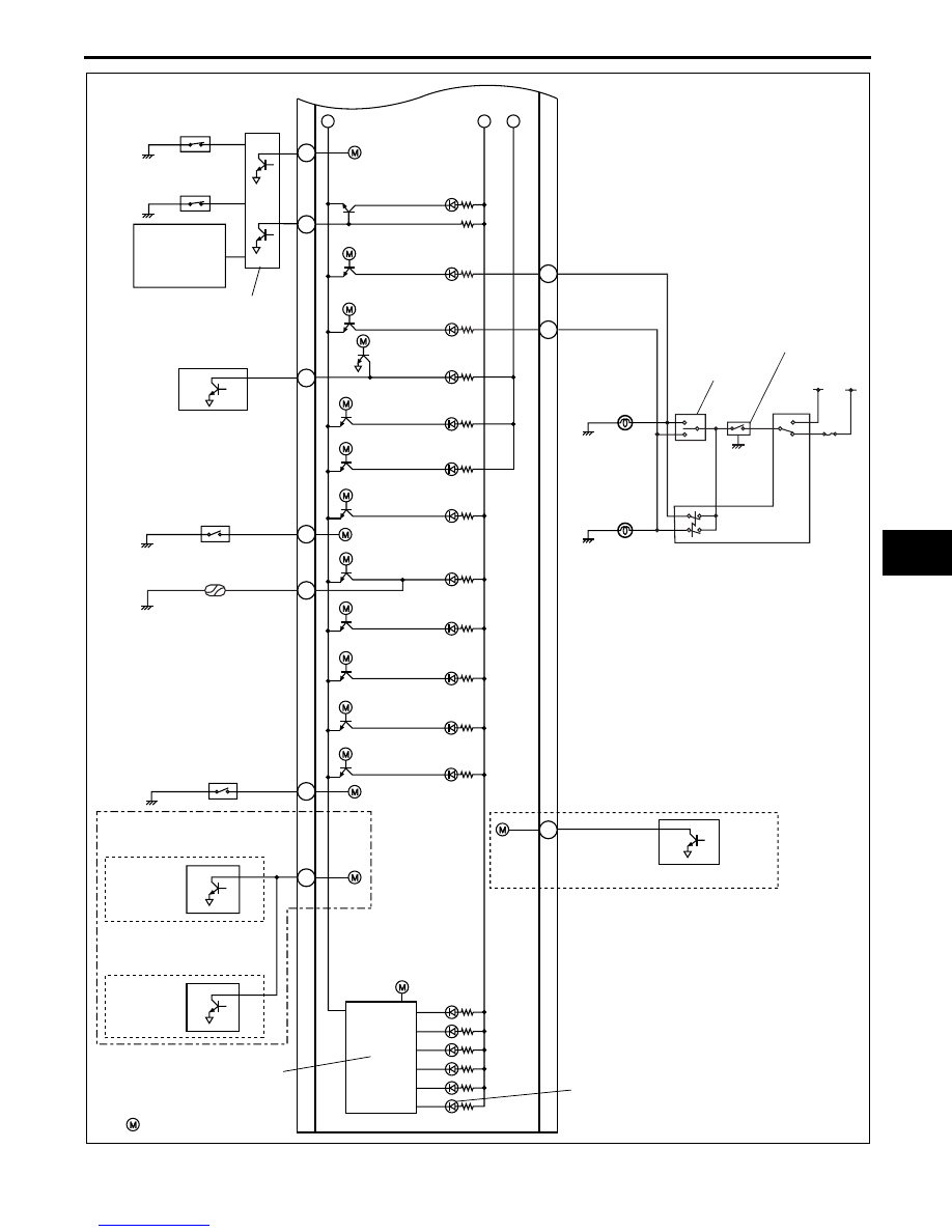
SAS CONTROL MODULE
OIL PRESSURE SWITCH
SECURITY LIGHT
GEAR POSITION INDICATOR
: TO MICROCOMPUTER
CRUISE SET
INDICATOR LIGHT
CRUISE MAIN
INDICATOR LIGHT
BRAKE SYSTEM
WARNING LIGHT
ABS WARNING
LIGHT
SELECTOR INDICATOR
DRIVE CIRCUIT
AIR BAG SYSTEM
WARNING LIGHT
TURN INDICATOR
LIGHT (LH)
TURN INDICATOR
LIGHT (RH)
2A
BUCKLE SWITCH
(DRIVER'S SIDE)
BUCKLE SWITCH
(PASSENGER'S SIDE)
SEAT WEIGHT
SENSOR
CONTROL
MODULE
IG1
B+
2I
2G
TURN SWITCH
HAZARD WARNING
SWITCH
FLASHER
CONTROL MODULE
TURN LIGHT
(LH)
TURN LIGHT
(RH)
2F
KEYLESS CONTROL MODULE
KEYLESS
CONTROL
MODULE
2U
KEYLESS
INDICATOR LIGHT
KEYLESS
WARNING LIGHT
BRAKE FLUID
LEVEL SENSOR
1D
PARKING BRAKE SWITCH
2M
TIRE PRESSURE
WARNING LIGHT
FLAT TIRE
WARNING LIGHT
WITH ADVANCED
KEYLESS SYSTEM OR
KEYLESS ENTRY SYSTEM
KEYLESS
RECEIVER
WITH TPMS
KEYLESS CONTROL MODULE
WITH ADVANCED
KEYLESS SYSTEM
WITHOUT ADVANCED
KEYLESS SYSTEM AND
KEYLESS ENTRY SYSTEM
E5U922ZS5003