Mazda X-5. Manual - part 80
AUTOMATIC TRANSMISSION [SJ6A-EL]
05–13–23
05–13
COMPONENT DESCRIPTIONS (ELECTRONIC CONTROL) [SJ6A-EL]
E5U051318901N04
End Of Sie
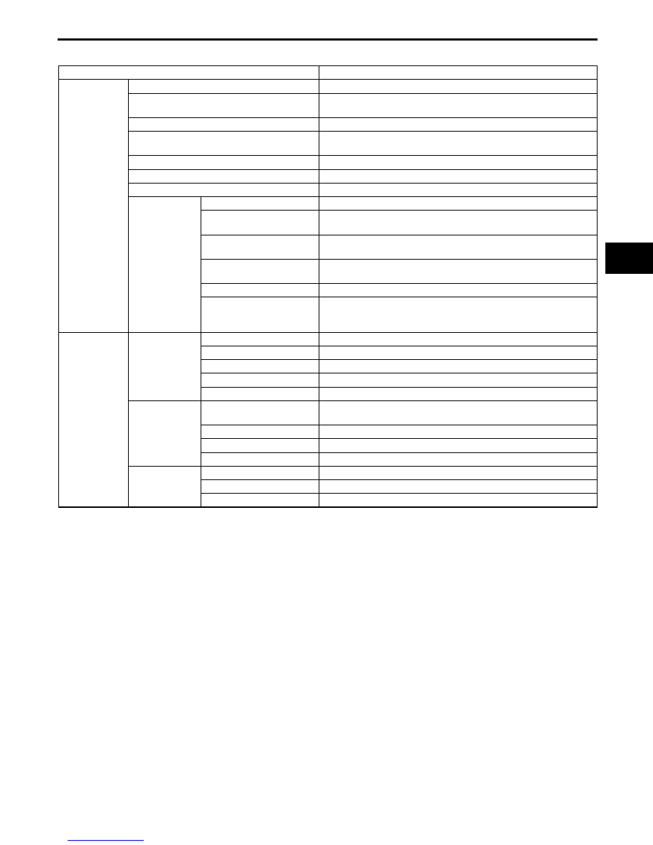
Part name
Function
Input system
VSS
• Detects parking gear (output) revolution speed.
Turbine sensor
• Detects direct and reverse disc clutch case (input) revolution
speed.
TR switch
• Detects selector lever ranges/positions.
M range switch
• Selects driving modes (M range) and changes driving
patterns.
Up switch
• Detects shift up request.
Down switch
• Detects shift down request.
TFT sensor
• Detects ATF temperature.
CAN
communication
Brake switch
• Detects the brake pedal depressed.
Throttle opening signal
(APP sensor)
• Input throttle opening angle from PCM.
Engine speed signal
(CKP sensor)
• Input engine speed signal from PCM.
Engine torque signal
(MAF sensor)
• Input engine torque signal from PCM.
Cruise control signal
• Detects cruise control is in use.
Engine coolant
temperature signal
(ECT sensor)
• Input engine coolant temperature signal from PCM.
Output system
ON/OFF type
Shift solenoid A
• Controls the clutch engagement pressure.
Shift solenoid B
• Controls the clutch engagement pressure.
Shift solenoid C
• Controls the clutch engagement pressure.
Shift solenoid D
• Controls the clutch engagement pressure.
Shift solenoid E
• Controls the clutch engagement pressure.
Linear type
Line pressure control
solenoid
• Adjusts the line pressure.
TCC control solenoid
• Controls the TCC hydraulic pressure.
Shift solenoid F
• Controls the clutch engagement pressure.
Shift solenoid G
• Controls the clutch engagement pressure.
CAN
communication
AT warning light
• Illuminates when failure is detected by diagnosis function.
Speedometer signal
• Outputs the vehicle speed signal to speedometer.
Reduce torque signal
• Sends signals to the PCM during shifting.