Mazda X-5. Manual - part 66


  Index      Mazda     Mazda X-5 - service repair manual 2006 year


Search            


Content   ..  64  65  66  67   ..


Mazda X-5. Manual - part 66


DYNAMIC STABILITY CONTROL 

04–15–15

04–15

DSC CONTROL OPERATION

E5U041543750N10

• When the DSC HU/CM determines that the vehicle has a strong oversteer or understeer tendency, engine 

output is lowered and, at the same time, it suppresses the yaw moment by affecting the braking of the front or 
rear wheels to inhibit the oversteer or understeer tendency.

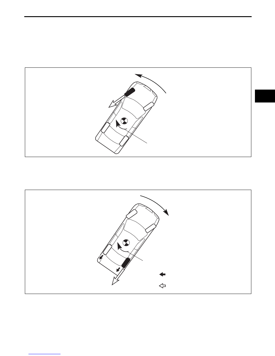
Oversteer Tendency Suppression

• When a large oversteer tendency is determined, braking is applied the outer front wheel according to the 

degree of the tendency. As a result, a yaw moment is formed towards the outer side of the vehicle and the 
oversteer tendency is suppressed.

Understeer Tendency Suppression

• When a large understeer tendency is determined, engine output is controlled and braking is applied to the inner 

front wheel according to the degree of the tendency. As a result, a yaw moment is formed towards the inner 
side of the vehicle and the understeer tendency is suppressed.

End Of Sie

RIGHT CORNERING

BRAKE FORCE FROM 
HYDRAULIC BRAKES

YAW MOMENTUM

OUTWARD YAW MOMENTUM

E5U415ZS5012

RIGHT CORNERING

INWARD YAW MOMENTUM

BRAKE FORCE FROM 
ENGINE BRAKING

BRAKE FORCE FROM 
HYDRAULIC BRAKES

YAW MOMENTUM

E5U415ZS5013

DYNAMIC STABILITY CONTROL 

04–15–16

CONTROLLER AREA NETWORK (CAN) OUTLINE

E5U041543750N11

• The DSC HU/CM sends and receives data to and from other modules via the CAN system. Refer to Section 09 

for a detailed explanation of the CAN system.

Data sent

• Travelled distance

• Brake system status

• Wheel speeds of all four wheels

• ABS wheel-speed sensor status

• Torque reduction request

Data received

• Engine speed

• Throttle valve opening angle

• Engine torque

• Torque reduction disabled

• Transmission/axle specifications

• Tire size

• Target gear position/selector lever position

• Steering angle

• Steering angle sensor status

• Parking brake position

End Of Sie

ABS WHEEL-SPEED SENSOR FUNCTION

E5U041543720N01

• The ABS wheel-speed sensor detects and transmits the rotation condition of each wheel to the DSC HU/CM.

• The signal from the ABS wheel-speed sensors is the primary signal for DSC HU/CM control.

End Of Sie

ABS WHEEL-SPEED SENSOR CONSTRUCTION/OPERATION

E5U041543720N02

• The construction and operation of the ABS wheel-speed sensor is the same as that of vehicles with ABS.

End Of Sie

COMBINED SENSOR FUNCTION

E5U041543773N01

• A combined sensor, which integrates the yaw rate and lateral-G sensors, has been adopted.

• The combined sensor, located in the floor under the rear console, detects the vehicle yaw rate (vehicle turning 

angular speed) and lateral-G, and transmits them to the DSC HU/CM.

End Of Sie

COMBINED SENSOR CONSTRUCTION/OPERATION

E5U041543773N02

• The combined sensor, with built-in yaw rate and 

lateral-G sensors, detects and calculates the 
vehicle yaw rate and lateral-G, converts them into 
voltage and transmits this to the DSC HU/CM.

• The output voltage characteristic for the 

combined sensor is 2.5 V when the vehicle is 
standing still, and changes accordingly as yaw 
rate and lateral-G are formed.

• The yaw rate sensor detects a Coriolis force 

created by, and in proportion to, the rotation 
speed of a rotating tuning fork.

• The lateral-G sensor detects an inertial force 

created by, and in proportion to, a G-force acting 
on a silicon detection component.

Note

• Coriolis force: When an object on a rotating disc attempts to move toward the center of the disc, force is 

produced at a right angle to the intended path of travel of the object. This results in the direction of 
movement being unchanged from its original point of departure, and the object does not reach the center. 
When looking at this effect from outside the disc, it appears as if a force is deflecting the object away from 
the center. This appearance of force is called a Coriolis force, and the object actually advances in a 
straight course.

End Of Sie

VEHICLE FRONT 

STRUCTUAL VIEW

E5U415ZS5014

DYNAMIC STABILITY CONTROL 

04–15–17

04–15

BRAKE FLUID PRESSURE SENSOR FUNCTION

E5U041543774N01

• The brake fluid pressure sensor detects the fluid pressure from the master cylinder and transmits it to the DSC 

HU/CM.

End Of Sie

BRAKE FLUID PRESSURE SENSOR CONSTRUCTION

E5U041543774N02

• The brake fluid pressure sensor is integrated with the DSC HU/CM. Therefore if there is any malfunction of the 

brake fluid pressure sensor, replace the DSC HU/CM.

End Of Sie

STEERING ANGLE SENSOR FUNCTION

E5U041566120N01

• The steering angle sensor, located on the combination switch, detects the steering angle degree and the 

neutral position, and transmits these to the DSC HU/CM via CAN lines.

Warning

• The following circumstances will cause the stored initialization value of the steering angle sensor 

to be cleared. This may possibly cause an accident due to the DSC becoming inoperative. Always 
refer to the Workshop Manual and properly perform the initialization procedure for the steering 
angle sensor so that the DSC operates properly.

— Negative battery cable disconnection

— Steering angle sensor connector disconnection

— Fuse (ROOM 15A) removal

— Wiring harness disconnection between battery and steering angle sensor connector

Note

• If the initialization procedure for the steering angle sensor has not been performed, when the ignition 

switch is turned to the ON position, the DSC indicator light illuminates and the DSC OFF light flashes to 
warn of a malfunction.

End Of Sie

STEERING ANGLE SENSOR CONSTRUCTION

E5U041566120N02

• The steering angle sensor, integrated with the 

combination switch body, has a sensor unit 
straddling a disc that moves together with the 
steering mechanism. Therefore, if there is any 
malfunction of the steering angle sensor, replace 
the combination switch body.

End Of Sie

DSC INDICATOR LIGHT FUNCTION

E5U041555430N01

• The DSC indicator light, built into the instrument cluster, informs the driver of the following vehicle conditions.

— DSC is operating (vehicle side-slip)

— TCS is operating (drive wheel slipping)

End Of Sie

SENSOR UNIT

DISC

CHU0415S015

DYNAMIC STABILITY CONTROL 

04–15–18

DSC INDICATOR LIGHT OPERATION

E5U041555430N02

• When the DSC and CAN lines are normal, the DSC indicator light illuminates for approx. 3 s when the ignition 

switch is turned to the ON position to check the light function. When the system is malfunctioning, the DSC 
indicator light remains illuminated.

• When the DSC or TCS is operating (DSC has not been disabled by pressing the DSC OFF switch), the DSC 

indicator light operates as follows: 

DSC Indicator Light Operation

End Of Sie

DSC OFF SWITCH, DSC OFF LIGHT FUNCTION

E5U041566410N01

• The DSC OFF switch, located on the dashboard, allows for optionally enabling/disabling the DSC control at 

driver discretion.

• The DSC OFF light, built into the instrument cluster, informs the driver that DSC control has been disabled by 

operation of the DSC OFF switch.

End Of Sie

DSC OFF SWITCH, DSC OFF LIGHT OPERATION

E5U041566410N02

• When the DSC system and CAN lines are functionally normally, the DSC OFF light illuminates for approx. 1.8 

s when the ignition switch is turned to the ON position to check the light function.

• When the DSC OFF switch is pressed to disable DSC control, the DSC OFF light illuminates.

Note

• When releasing the DSC, continue to press the DSC OFF switch until the DSC OFF light illuminates.

End Of Sie

Item

DSC indicator light condition

TCS, DSC not operating

Not illuminated

TCS operating

Flashes (0.5 s intervals)

DSC operating

BRAKE

DSC INDICATOR LIGHT

E5U415ZS5015

BRAKE

DSC OFF LIGHT

DSC OFF SWITCH

E5U415ZS5016


Content   ..  64  65  66  67   ..