Mazda X-5. Manual - part 36


  Index      Mazda     Mazda X-5 - service repair manual 2006 year


Search            


Content   ..  34  35  36  37   ..


Mazda X-5. Manual - part 36


CONTROL SYSTEM 

01–40–17

01–40

Maximum Cam Retard Mode
Mode execution condition

• When any of the following conditions are met:

— Cranking

— Idling after completion of cleaning mode

— DTC stored for the following devices:

• ECT sensor

• CKP sensor

• CMP sensor

• TP sensor

• MAF sensor

• OCV

Purpose

• Maximum cam retard mode stabilizes engine speed by maximally retarding the valve timing when the engine 

speed is low during idling.

Operation

• When the target current in the maximum cam retard mode is fixed at 100 mA. When 100 mA current is 

supplied, the OCV opens the hydraulic passage for the retard chamber and hydraulic pressure from the oil 
pump is introduced to the retard chamber. Because of this, the variable valve timing actuator is fixed at the 
maximum retard position (minimum overlap).

Feedback Hold Mode
Mode execution condition 

• Target valve timing and actual valve timing are almost the same.

Purpose

• The feedback hold mode holds the valve timing by returning the OCV spool valve to the neutral position when 

target valve timing suitable for the engine operation conditions is obtained.

Operation

• Though the target current in the feedback hold mode is basically around 600 mA, feedback operation is 

performed at all times so that the present OCV drive current approaches the target current. Because the hold 
current changes due to mechanical variation between engines and deterioration due to aging on OCV internal 
parts, the PCM continues to learn the changing current (hold current learning value) to maintain the spool valve 
in the neutral position.

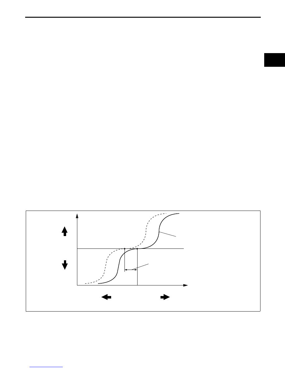
ADVANCE SPEED INCREASES
AS INCLINATION INCREASES

CHANGES ACCORDING TO MECHANICAL
VARIANCE AND AGED DETERIORATION

ADVANCE

RETARD

APPROX. 100 mA

APPROX. 600 mA

APPROX. 1,000 mA

OCV OPERATION CURRENT

E5U140ZT5101

CONTROL SYSTEM 

01–40–18

Feedback Mode
Mode execution condition

• Except during cleaning, maximum cam retard, or feedback hold modes.

Purpose

• Feedback mode obtains valve timing suitable for engine operation conditions by performing the feedback 

operation so that present OCV drive current is set closer to the target current determined by the PCM 
according to engine operation conditions.

Operation

• Based on engine operation conditions, the target current is set between 100 mA (maximum retard) and 1,000 

mA (maximum advance), using the neutral point of approx. 600 mA as a reference. Actually, the target current 
is calculated by subtracting the current necessary for obtaining the target advance/retard amount, using a 
reference at the hold-current learning value calculated from the neutral position of the spool valve.

Advance Spark Speed Correction

• If there is a large difference between the target valve timing and the actual valve timing, the target current 

correction is applied so that it is set closer to the target valve timing more quickly to raise the advance spark 
speed by advancing the spool valve initialization operation.

• The variable valve timing actuator advance spark speed increases as the hydraulic passage in the OCV widens 

and decreases as it narrows.

Valve Timing Determination

• The PCM controls current to the OCV to obtain optimum valve timing suitable for the engine operation 

conditions (target valve timing).

• The PCM compares target valve timing with actual valve timing, and feeds back the result to change valve 

timing smoothly.

Target valve timing

• Determined according to engine speed and charging efficiency.

Actual valve timing

• Means present valve timing. Actual valve timing is calculated by adding the maximum cam retard learning value 

for energization from the value detected by the CMP and CKP sensors.

Cam maximum retard learning value

• Though the intake camshaft valve timing (including maximum retard position) is detected based on the 

difference between the signal from the sensor and signal from the CKP sensor, the difference between the 
signals deviates due to the sensor installation condition. Because of this, the PCM stores the difference 
between the signal build-ups at the maximum OCV retard position to prevent deviation in valve timing detection.

End Of Sie

FUEL INJECTION CONTROL OUTLINE [LF]

E5U014000000N25

• Performs optimum fuel injection according to engine operation conditions.

• The PCM determines the engine operation conditions based on the signals from the following input devices and 

drives the injectors at the optimum fuel injection time (fuel injection amount) and the fuel injection timing to 
inject fuel. For the construction/operation of the fuel injector, refer to “FUEL SYSTEM, FUEL INJECTOR 
CONSTRUCTION/OPERATION”.

End Of Sie

CONTROL SYSTEM 

01–40–19

01–40

FUEL INJECTION CONTROL BLOCK DIAGRAM [LF]

E5U014000000N26

End Of Sie

IAT SENSOR

MAF SENSOR

MAP SENSOR

CMP SENSOR

ECT SENSOR

CKP SENSOR

BARO SENSOR

NEUTRAL SWITCH (MT)

CPP SWITCH (MT)

BRAKE SWITCH 

NO.1, NO.2

A/C AMPLIFIER 

REFRIGERANT PRESSURE 

SWITCH (MIDDLE)

REFRIGERANT  PRESSURE 

     SWITCH (LOW, HIGH)

BATTERY

VEHICLE SPEED 

SIGNAL

TR SWITCH (AT)

SYNCHRONIZED 
FUEL INJECTION

EFFECTIVE 
INJECTION TIME

INJECTION 
TIME AT 
ENGINE START

BASIC 
INJECTION TIME

VARIOUS 
CORRECTION 
TYPES

INEFFECTIVE 
INJECTION TIME

NON-SYNCHRONIZED 
INJECTION CONTROL

INEFFECTIVE 
INJECTION TIME

FUEL INJECTOR ENERGIZATION 
TIMING AND ENERGIZATION 
TIME

FUEL INJECTOR

PCM

FRONT HO2S

TP SENSOR NO.1, NO.2

APP SENSOR NO.1, NO.2

REAR HO2S 

E5U140ZT5003

CONTROL SYSTEM 

01–40–20

FUEL INJECTION CONTROL OPERATION [LF]

E5U014000000N27

Operation
Injection timing

• There is synchronized fuel injection, which performs fuel injection by the setting of the crankshaft position, and 

non-synchronized fuel injection which performs fuel injection when the condition for fuel injection is met 
regardless of the crankshaft position.

Synchronized fuel injection

• The crankshaft rotation is synchronized by each intake and exhaust stroke of the cylinders, and fuel injection is 

performed by the fuel injection timing and the injection amount corresponding to the input signals of the 
following sensors.

— CKP sensor, MAF sensor, ECT sensor, IAT sensor

Non-synchronized fuel injection

• The crankshaft rotation is not synchronized and fuel injection is performed by the injection timing and injection 

amount as triggered by the input signals of the following sensors.

— TP sensor, MAF sensor, ECT sensor, IAT sensor

Relation between synchronized and non-synchronized fuel injection

• If synchronized and non-synchronized fuel injection happen to occur together, fuel is injected by adding the fuel 

injection timing of both.

Injection Time

• The PCM calculates the fuel injection amount according to the engine operation conditions as the fuel injection 

time and energizes the fuel injectors.

Fuel injector energization time and operation conditions

• The fuel injectors cause an operation delay with 

the start of energization from the PCM. The PCM 
calculates the fuel injection time by adding the 
non-injection time (ineffective injection time) with 
the actual injection time (effective injection time), 
and energizes the fuel injectors for this time.

• The fuel injection time is based on the following 

formula:
Fuel injection time = effective injection time + 
ineffective injection time
Ineffective injection time

— The fuel injectors cause a delay in operation 

due to a delay in the build-up of operation 
current from coil inductance with the start of 
energization, and by the mass of the needle 
valve and plunger, and spring resistance. This 
delay is the ineffective injection time.

— The non-injection time is affected by the 

change in battery voltage. Accordingly, the 
PCM sets the non-injection time according to 
the battery voltage

Effective injection time

— The fuel injector opening valve time which is 

the actual fuel injection time is called the 
effective injection amount.

ON

OFF

0

INJECTION 
SIGNAL

FUEL INJECTOR 
CURRENT

FUEL INJECTOR

FUEL INJECTION TIME

INEFFECTIVE 
INJECTION TIME

EFFECTIVE 
INJECTION TIME

FUEL INJECTOR OPENING 
VALVE ELECTRICAL 
CURRENT

FUEL INJECTOR VALVE 
OPENING TIME

OPEN

CLOSED

C3U0140S014


Content   ..  34  35  36  37   ..