Mazda X-5. Manual - part 23


  Index      Mazda     Mazda X-5 - service repair manual 2006 year


Search            


Content   ..  21  22  23  24   ..


Mazda X-5. Manual - part 23


FUEL SYSTEM 

01–14–5

01–14

FUEL PUMP UNIT FUNCTION [LF]

E5U011413350N01

• The fuel pump siphons fuel from the fuel tank and pumps it to the fuel injectors.

End Of Sie

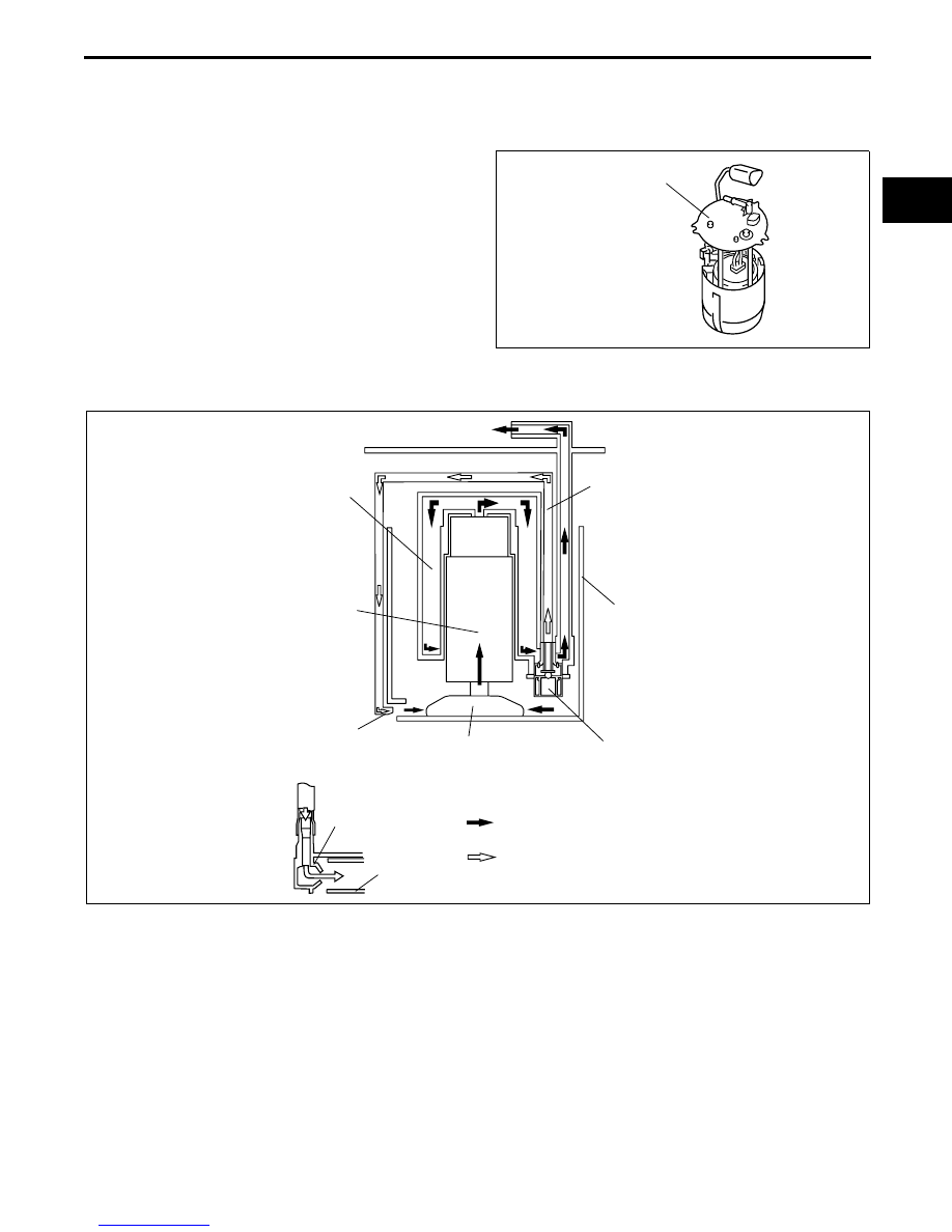
FUEL PUMP UNIT CONSTRUCTION/OPERATION [LF]

E5U011413350N02

Fuel Pump Unit

• Mainly consists of a fuel filter (high-pressure), 

pressure regulator, fuel pump, fuel reserve cup, 
and fuel filter (low-pressure).

• A pressure regulator is built-in due to the adoption 

of a returnees fuel system.

• A hard-plastic fuel pump unit, with an integrated 

fuel filter (high-pressure) and fuel pump, has been 
adopted to simplify the fuel line.

• The fuel pump unit can be disassembled.

• Fuel in the fuel reserve cup is sectioned out 

through the fuel filter (low-pressure) by the fuel 
pump, and pumped to the fuel filter (high-
pressure). Return fuel is sent back to the fuel reserve cup or the fuel tank through the jet pump.

Pressure Regulator

• Built into the fuel pump unit due to adoption of a returnees fuel system.

• Mainly consists of a spring, release valve and diaphragm.

• Pressurizes fuel discharged by the fuel pump to approx. 390 kPa {3.98 kgf/cm

2

, 56.6 psi} using the spring, 

diaphragm and release valve, and then pumps it to the fuel distributor.

• If fuel pressure exceeds approx. 390 kPa {3.98 kgf/cm

2

, 56.6 psi}, the release valve opens to discharge 

unnecessary fuel pressure.

End Of Sie

FUEL PUMP UNIT

E5U114ZS5022

PRESSURE 
REGULATOR

RESERVOIR CUP

FUEL FILTER 
(LOW-PRESSURE)

JET PUMP

FUEL PUMP

RESERVOIR 
CUP

JET PUMP

: PUMPED FUEL FLOW TO      
  FUEL DISTRIBUTOR

: RETURN FUEL FLOW FROM 
  PRESSURE REGULATOR

FUEL FILTER 
(HIGH-PRESSURE)

E5U114ZS5002

FUEL SYSTEM 

01–14–6

QUICK RELEASE CONNECTOR (FUEL SYSTEM) FUNCTION [LF]

E5U011442692N01

• Quick release connectors that can be easily connected/disconnected have been adopted to improve 

serviceability.

End Of Sie

QUICK RELEASE CONNECTOR (FUEL SYSTEM) CONSTRUCTION/OPERATION [LF]

E5U011442692N02

• There are two types of quick release connectors.

Quick release connector locations

Type A

• Used in the engine compartment.

• An SST is not used with this type.

• Mainly consists of a retainer and O-ring. The quick release connector is integrated with the fuel hose and 

therefore cannot be disassembled.

• When the quick release connector is connected, 

the fuel pipe projection is locked at the clamp lock 
point. By pushing the clamp release tab to 
expand the clamp, the lock point is released 
allowing the fuel pipe to be disconnected.

• To connect the quick release connector properly, 

push it into the fuel pipe until a locking click sound 
is heard.

• New quick release connectors are fitted with a 

checker tab that prevents improper fit. This 
checker tab cannot normally be removed. When 
the quick release connector is properly connected 
to the fuel pipe, the lock is released and the 
checker tab comes off. Due to this, it can be 
verified that the quick release connector is 
completely connected.

TYPE A

TYPE B

FUEL PUMP UNIT

FUEL TANK SIDE

ENGINE COMPARTMENT SIDE

E5U114ZW5011

QUICK RELEASE CONNECTOR

RELEASE TAB

LOCK POINT

C3U0114S091

FUEL PIPE

CHECKER TAB

C3U0114S092

FUEL SYSTEM 

01–14–7

01–14

Type B

• The connector can be disconnected by pinching 

the retainer tab with the SST and pulling the 
connector.

• To connect the quick release connector properly, 

push it into the fuel pipe until a locking click sound 
is heard.

• New quick release connectors are fitted with a 

checker tab that prevents improper fit. This 
checker tab cannot normally be removed. When 
the quick release connector is properly connected 
to the fuel pipe, the lock is released and the 
checker tab comes off. Due to this, it can be 
verified that the quick release connector is 
completely connected.

End Of Sie

SST

E5U114ZW5003

CHECKER TAB

FUEL PIPE

E5U114ZS5004

FUEL SYSTEM 

01–14–8

FUEL INJECTOR FUNCTION [LF]

E5U011413250N01

• Injects fuel according to fuel injector control signals from the PCM.

End Of Sie

FUEL INJECTOR CONSTRUCTION/OPERATION [LF]

E5U011413250N02

• Installed on the cylinder head. 

• Mainly consists of a coil, spring, needle valve and ball.

• A signal is sent from the PCM causes excitation current to pass through the coil and thereby pull in the needle 

valve. Since the ball that opens and closes the injection opening is integrated with the needle valve, it is pulled 
together with the needle valve and fuel is injected.

• The amount of injection is determined by the 

open time of the needle valve (equal to the 
energization time of the coil).

End Of Sie

FUEL PUMP RELAY FUNCTION [LF]

E5U011400000N06

• Controls the fuel pump on/off according to control signals from the PCM.

End Of Sie

COIL

SPRING

NEEDLE VALVE

BALL

O-RING

O-RING

C3U0114S111


Content   ..  21  22  23  24   ..