Mazda X-5. Manual - part 8


  Index      Mazda     Mazda X-5 - service repair manual 2006 year


Search            


Content   ..  6  7  8  9   ..


Mazda X-5. Manual - part 8


ON-BOARD DIAGNOSTIC 

01–02–9

01–02

*1

: California emission regulation applicable model

*2

: MT

*3

: C: CMDTC self-test, O: KOEO self-test, R: KOER self-test

*4

: With ABS/DSC or MT without ABS/DSC
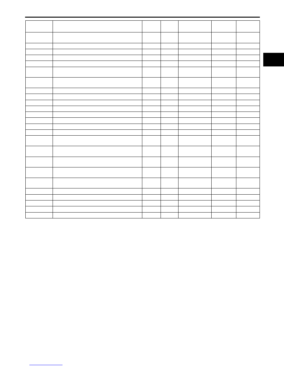
P2119

Throttle actuator control throttle body range/
performance problem

ON

2

CCM

C, R

×

P2122

APP sensor No.1 circuit low input

ON

1

CCM

C, O, R

×

P2123

APP sensor No.1 circuit high input

ON

1

CCM

C, O, R

×

P2127

APP sensor No.2 circuit low input

ON

1

CCM

C, O, R

×

P2128

APP sensor No.2 circuit high input

ON

1

CCM

C, O, R

×

P2135

TP sensor No.1/No.2 voltage correlation 
problem

ON

1

CCM

C, O, R

×

P2138

APP sensor No.1/No.2 voltage correlation 
problem

ON

1

CCM

C, O, R

×

P2177

Fuel system too lean at off idle

ON

2

Fuel system

C, R

×

P2178

Fuel system too rich at off idle

ON

2

Fuel system

C, R

×

P2187

Fuel system too lean at idle

ON

2

Fuel system

C, R

×

P2188

Fuel system too rich at idle

ON

2

Fuel system

C, R

×

P2195

Front HO2S signal stuck lean

ON

2

HO2S

C

×

P2196

Front HO2S signal stuck rich

ON

2

HO2S

C

×

P2228

BARO sensor circuit low input

ON

1

CCM

C, O, R

×

P2229

BARO sensor circuit high input

ON

1

CCM

C, O, R

×

P2401

EVAP system leak detection pump motor 
circuit low

ON

2

CCM

C, R

×

P2402

EVAP system leak detection pump motor 
circuit high

ON

2

CCM

C, R

×

P2404

EVAP system leak detection pump sense 
circuit problem

ON

2

CCM

C, R

×

P2405

EVAP system leak detection pump sense 
circuit low input

ON

2

CCM

C, R

×

P2407

EVAP system leak detection pump sense 
circuit intermittent

ON

2

CCM

C, R

×

P2502

Charging system voltage problem

OFF

1

Other

C, R

×

P2503

Charging system voltage low

OFF

1

Other

C, R

×

P2504

Charging system voltage high

OFF

1

Other

C, R

×

P2507

PCM B+ voltage low

ON

1

CCM

C, O, R

×

P2610

PCM internal engine off timer performance

ON

2

CCM

C

×

DTC No.

Condition

MIL

DC

Monitor item

 Self-test 

type*

3

Memory 

function

ON-BOARD DIAGNOSTIC 

01–02–10

Sending Intermittent Monitoring System Test Results

• The items supported by the sending intermittent monitoring system are shown below.

*

1

: California emission regulation applicable model

Sending Continuous Monitoring System Test Results

• These appear when a problem is detected in a monitored system.

1-drive cycle type

• If any problems are detected in the first drive cycle, pending codes will be stored in the PCM memory, as well 

as DTCs.

• After pending codes are stored, if the PCM determines that the system is normal in any future drive cycle, the 

PCM deletes the pending codes.

2-drive cycle type

• The code for a failed system is stored in the PCM memory in the first drive cycle. If the problem is not found in 

the second drive cycle, the PCM determines that the system returned to normal or the problem was mistakenly 
detected, and deletes the pending code when the ignition switch is turned to the ON position in the next drive 
cycle. If the problem is found in the second drive cycle too, the PCM determines that the system has failed, and 
stores the pending codes, and the DTCs.

• After pending codes are stored, if the PCM determines that the system is normal in any future drive cycle, the 

PCM deletes the pending codes.

DLC-2 Outline

• The DLC-2 located in the driver compartment is a service connector defined by OBD-II regulations.

• The following are functions for each terminal.

End Of Sie

TEST ID

Description

Related system

10:01:84

HO2S (Front) period (calculated)

HO2S

10:02:03

Low HO2S (Rear) voltage for switch time calculation (constant)

10:02:04

High HO2S (Rear) voltage for switch time calculation (constant)

10:02:05

HO2S (Rear) rich-to-lean response time (calculated)

10:21:80

HO2S (Front) and HO2S (Rear) switching time ratio

Catalyst

10:31:83

EGR pressure variation

EGR

10:3A:80

EVAP system leak detection pump large leak check

EVAP

10:3B:80

EVAP system leak detection pump small leak check

10:3C:80

*1

EVAP system leak detection pump very small leak check

10:3D:80

Purge flow monitor

10:A2:0B

Cylinder No.1 average misfire counts for last 10 DC 

Misfire

10:A2:0C

Cylinder No.1 misfire counts for last/current DC

10:A3:0B

Cylinder No.2 average misfire counts for last 10 DC 

10:A3:0C

Cylinder No.2 misfire counts for last/current DC

10:A4:0B

Cylinder No.3 average misfire counts for last 10 DC 

10:A4:0C

Cylinder No.3 misfire counts for last/current DC

10:A5:0B

Cylinder No.4 average misfire counts for last 10 DC 

10:A5:0C

Cylinder No.4 misfire counts for last/current DC

10:E1:80

Heat radiation ratio

Thermostat

10:E1:81

Engine coolant temperature

Terminal name

Function

B+

Battery positive voltage

CAN_L

Serial communication Lo terminal

CAN_H

Serial communication Hi terminal

GND1

Ground (chassis)

GND2

Ground (signal)

+B

CAN_L

GND1

CAN_H GND2

DLC-2

E5U102ZS4001

ON-BOARD DIAGNOSTIC 

01–02–11

01–02

DTC DETECTION LOGIC AND CONDITIONS [LF]

E5U010200000N03

B1342 PCM malfunction

• Malfunction in the PCM internal circuit.

P0011 CMP Timing over-advanced

• The actual valve timing is over-advanced by 15 ° from the target valve timing for specified period when the oil 

control valve (OCV) is controlled in the maximum valve timing retard condition.
Monitoring condition

— Engine coolant temperature is above 63 

°C {145.4 °F}

P0012 CMP timing over-retarded

• Actual valve timing is over-retarded by 10 ° from the target valve timing for specified period when the oil control 

valve (OCV) system control is within the feedback range.
Monitoring condition

— Engine coolant temperature is above 63 

°C {145.4 °F}

P0016 CKP-CMP correlation

• The PCM monitors the input pulses from the CKP sensor and CMP sensor. If the input pulse pick-up timing do 

not match each other, the PCM determines that the camshaft position does not coincide with the crankshaft 
position.

P0030 Front HO2S heater control circuit problem

• The PCM monitors the front HO2S impedance when under the front HO2S heater control for 200 s. If the 

impedance is more than 44 ohms, the PCM determines that there is a front HO2S heater control circuit 
problem.

P0031 Front HO2S heater circuit low input

• The PCM monitors the front HO2S heater control voltage when the PCM turns the front HO2S heater off. If the 

control voltage exceeds 50% of the battery voltage, the PCM determines that the front HO2S heater control 
circuit voltage is low.

P0032 Front HO2S heater circuit high input

• The PCM monitors the front HO2S heater control voltage when the PCM turns the front HO2S heater on. If the 

control voltage is less than 50% of the battery voltage, the PCM determines that the front HO2S heater control 
circuit voltage is high.

P0037 Rear HO2S heater circuit low input

• The PCM monitors the rear HO2S heater control voltage when the PCM turns the rear HO2S heater off. If the 

control voltage exceeds 25% of the battery voltage, the PCM determines that the rear HO2S heater control 
circuit voltage is low.

P0038 Rear HO2S heater circuit high input

• The PCM monitors the rear HO2S heater control voltage when the PCM turns the rear HO2S heater on. If the 

control voltage is less than 57% of the battery voltage, the PCM determines that the rear HO2S heater control 
circuit voltage is high.

P0069 Manifold absolute pressure/atmospheric pressure correlation

• PCM monitors differences between intake manifold vacuum and atmospheric pressure. If the difference is 

below –12 kPa {–90 mmHg, –3.5 inHg} or above 12 kPa {90 mmHg, 3.5 inHg} when the following conditions 
are met, the PCM determines that there is a MAP sensor performance problem.
MONITORING CONDITION

— 12—15 s from when ignition switch is turned off.

— Intake air temperature is above -10

°C {14°F}.

— Engine coolant temperature is above 70

°C {158°F}.

P0101 MAF sensor circuit range/performance problem

• PCM monitors mass intake air flow amount when the engine is running.

— If the mass intake air flow amount is above 37 l/s for 5 s and the engine speed is below 2,000 rpm with the 

engine running, the PCM determines that the detected mass intake air flow amount is too high.

— If the mass intake air flow amount is below 4.4—59 l/s (The value depends on engine speed.) for 5 s and 

the engine speed is above 1,000 rpm with the engine running and the throttle opening angle above 50 %
the PCM determines that detected the mass intake air flow amount is too low.

P0102 MAF sensor circuit low input

• The PCM monitors input voltage from the MAF sensor when the engine running. If the input voltage is below 

0.21 V, the PCM determines that the MAF circuit has a malfunction.

P0103 MAF sensor circuit high input

• The PCM monitors the input voltage from the MAF sensor when the engine running. If the input voltage is 

above 4.92 V, the PCM determines that the MAF circuit has a malfunction.

P0107 MAP sensor circuit low input

• The PCM monitors the input voltage from the MAP sensor when intake air temperature is above –10 °C {14 

°F}. If the input voltage is below 0.1 V, the PCM determines that the MAP sensor circuit has a malfunction.
MONITORING CONDITIONS

— Calculated load: 13—32 %

ON-BOARD DIAGNOSTIC 

01–02–12

P0108 MAP sensor circuit high input

• The PCM monitors the input voltage from the MAP sensor when intake air temperature is above –10 °C {14 

°F}. If input the voltage is above 4.92 V, the PCM determines that the MAP sensor circuit has a malfunction.
MONITORING CONDITIONS

— Calculated load: 13—32 %

P0111 IAT sensor circuit range/performance problem

• If intake air temperature is higher than engine coolant temperature by 18 °C {32.4 °F} for 1.2 s with ignition 

switch on

*

, the PCM determines that there is a intake air temperature sensor circuit range/performance 

problem.

*: Ignition switch on when 6 h or more has passed since the previous ignition switch off
P0112 IAT sensor circuit low input

• The PCM monitors the IAT sensor signal. If the PCM detects that the IAT sensor voltage is below 0.16 V, the 

PCM determines that the IAT sensor circuit has a malfunction.

P0113 IAT sensor circuit high input

• The PCM monitors the IAT sensor signal. If the PCM detects that the IAT sensor voltage is above 4.84 V, the 

PCM determines that IAT sensor circuit has a malfunction. 

P0116 Engine coolant temperature circuit range/performance

• The PCM monitors the maximum value and minimum value of engine coolant temperature when the engine is 

started and 5 min have been passed after leaving the vehicle 6 h or more. If difference between maximum and 
minimum values of engine coolant temperature is below 6 

°C {10.8 °F} the PCM determines that there is an 

ECT circuit range/performance problem.

P0117 ECT sensor circuit low input

• The PCM monitors the ECT sensor signal at PCM terminal 2AH. If the PCM detects the ECT sensor voltage 

below 0.2 V, the PCM determines that the ECT sensor circuit has malfunction.

P0118 ECT sensor circuit high input

• The PCM monitors the ECT sensor signal at PCM terminal 2AH. If the PCM detects the ECT sensor voltage is 

above 4.58 V, the PCM determines that the ECT sensor circuit has malfunction.

P0122 TP sensor No.1 circuit low input

• If the PCM detects that the TP sensor No.1 voltage is below 0.1 V while the engine is running, the PCM 

determines that the TP sensor No.1 circuit has a malfunction.

P0123 TP sensor No.1 circuit high input

• If the PCM detects the TP sensor No.1 voltage is to be above 4.9 V after ignition switch to the ON position, 

PCM determines that TP sensor No.1 circuit has a malfunction.

P0125 Excessive time to enter closed loop fuel control

• The PCM monitors the ECT sensor signal at PCM terminal 2AK after engine is started while the engine is cold. 

If the engine coolant temperature does not reach the expected temperature for specified period, the PCM 
determines that it has taken an excessive amount of time for the engine coolant temperature to reach the 
temperature necessary to start closed-loop fuel control.

P0126 Coolant thermostat stuck open

• If the ECT signal never exceeds 71 °C {160 °F} after engine start for specified period, PCM determines that the 

coolant thermostat is stuck open.
MONITORING CONDITIONS

— IAT: above –10 

°C {14 °F}

— Vehicle speed: over 6 km/h {3.7 mph}

P0128 Coolant thermostat stuck open

• PCM monitors MAF, IAT, VSS and EAT signals and calculate radiator’s heat radiation ratio while following 

monitoring conditions are met. If calculated value exceeds threshold, PCM determines that the coolant 
thermostat is stuck open.
MONITORING CONDITIONS

— IAT: above –10

°C {14 °F}

— ECT at engine start: Below 36 

°C {97 °F}

— Difference between ECT at engine start and minimum IAT: Below 6 

°C {10.8 °F}

— Vehicle speed: over 30 km/h {18.6 mph}

P0130 Front HO2S circuit problem

• The PCM monitors the front HO2S impedance when under the front HO2S heater control. If the impedance is 

more than 500 ohms, the PCM determines that there is a front HO2S circuit problem.

P0131 Front HO2S circuit low input

• The PCM monitors the input voltage from the front HO2S and the front HO2S output current when the engine is 

running. If the input voltage is less than 1.8 V or the output current is less than –5 mA, the PCM determines 
that the front HO2S circuit voltage is low.

P0132 Front HO2S circuit high input

• The PCM monitors the input voltage from the front HO2S and the front HO2S output current when the engine is 

running. If the input voltage is more than 3.8 V or the output current is more than 5 mA, the PCM determines 
that the front HO2S circuit voltage is high.


Content   ..  6  7  8  9   ..